
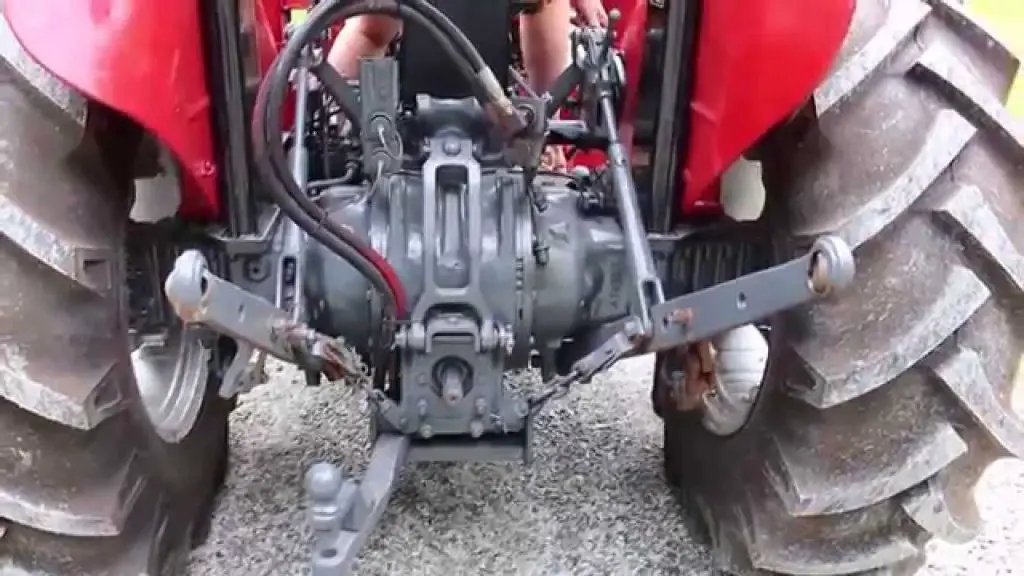
A Massey Ferguson three-point hitch that refuses to move does not automatically need a new hydraulic pump. The problem may be a control setting, an interrupted oil supply, an implement that exceeds the tractor’s working capacity, a mechanical obstruction or an internal fault. The first useful distinction is whether the hitch will not raise, will not lower, or moves but cannot hold its position.

Those symptoms involve different parts of the system. A hitch that lifts an empty linkage but not a loaded implement needs a different investigation from one that remains raised with the engine stopped. Likewise, a linkage that responds to an external button but ignores the cab control provides information that a completely inactive system does not.
This guide helps you organise those checks and recognise when pressure testing, electrical diagnosis or internal repair is needed. It covers several Massey Ferguson generations, so model-specific examples are labelled. It does not treat every MF tractor as having the same pump, reservoir, lever arrangement or electronic controls.
Identify the Tractor and Its Hydraulic System First
Record the full model, serial number, transmission type and fitted controls. An MF135, a GC compact and a modern tractor with Electronic Linkage Control can all carry a three-point implement, but their operating and diagnostic procedures differ. Market specification and optional equipment can also change what is installed on tractors carrying similar model names.
Use the correct operator’s manual to identify controls, oil requirements and maintenance points. Massey Ferguson’s Service and Information resource provides a route to operator manuals and equipment-specific support. For an older tractor, obtain the manual that matches its actual version rather than relying on a generic diagram of a similar machine.
An implement attachment is not necessarily a separate hydraulic system with its own oil tank. Many tractors use shared transmission and hydraulic oil arrangements. Others divide functions between pumps or circuits. Identify the correct fill and checking points before adding oil; filling an unrelated compartment cannot restore supply to the hitch.
Mechanical Controls and Electronic Controls Need Different Checks
Older Ferguson systems can have position, draft and response controls, with additional functions on some versions. Modern ELC systems can include height limits, lowering-rate settings, transport functions and external lift/lower buttons. A limit selected by the operator can look like lost lift travel even when the hydraulics are working.
Compact models should be checked by their actual control type too. Do not assume that every lever is a position control that holds a height corresponding to a mark on a quadrant. Read how the fitted lever commands movement, and identify any rate-of-drop adjustment separately. A control that governs lowering is not automatically a hydraulic pressure adjustment.
For example, MF’s GC1705/GC1710/GC1715/GC1720 product information describes a spring-centred hitch lever: moving it commands raising or lowering, and releasing it returns it to neutral to stop movement. It also identifies a separate drop-rate knob below the seat. That differs from selecting a fixed height with a conventional position-control quadrant. Check the exact GC model before applying this example to another generation.
- Photograph the control labels before changing settings.
- Note whether the fault began after attaching an implement, servicing the tractor or removing a loader or backhoe.
- Record whether the hitch works differently cold and warm, loaded and unloaded, or with different controls.
- Keep the implement model, approximate working weight and any quick-hitch adapter in the record.
Make the Tractor Safe Before Investigating
Park on firm, level ground, secure the tractor against movement and lower the implement wherever possible. Stop the engine, remove the key and disengage the PTO before inspecting, adjusting or uncoupling equipment. Follow the machine’s procedure for relieving stored pressure; stopping the engine does not guarantee that every part of a hydraulic circuit is depressurised.
Never work beneath an implement supported only by the hitch hydraulics. Use the approved mechanical support or a properly rated support arrangement specified for the task. A closed lowering valve or transport lock is not a substitute for secure support during maintenance. If the attachment cannot be lowered or supported safely, have a qualified technician organise recovery.
Keep hands away from suspected hydraulic leaks. A fine jet can penetrate skin, and an apparently small injection wound needs immediate professional medical attention. The HSE’s hydraulic-fluid guidance explains why looking for leaks with bare hands and opening pressurised connections are dangerous.
Do not stand between the tractor and implement while another person experiments with controls. For operational observations, use the normal operator position and keep everyone outside the movement area. External hitch buttons require the stance and clearance described in the manual. A video taken from a safe position can document movement without placing someone alongside a pinch point.
Match the Symptom to the First Checks
| Hitch behaviour | Check before assuming an internal failure | What the result can help separate |
|---|---|---|
| Will not rise at all | Controls, locks, oil level and any recently changed hydraulic connections | Missing command or supply versus a hitch-specific fault |
| Raises empty arms but not the implement | Actual load, lift geometry and correct operating settings | Excessive demand versus inadequate hydraulic performance |
| Lifts slowly or becomes weak when warm | Oil specification, service history, restrictions and operating conditions | Supply problems versus leakage or wear |
| Stays raised when lowering is selected | Lowering control, transport setting and mechanical interference | A blocked lowering path versus an obstruction |
| Drops too quickly | Rate-of-drop setting and control response | Adjustment versus loss of control |
| Sinks or repeatedly corrects itself | External leakage and a safely observed movement pattern | Oil escaping from the holding circuit versus commanded movement |
| Stops at the same intermediate height | Lift limit, control travel and implement clearance | Deliberate limitation or binding versus loss of lifting force |
| One side sits lower | Levelling adjustment, pins, lift rods and implement setup | Geometry or damage versus a hydraulic problem |
| Cab control fails but another control works | Control settings, warnings and the manual’s enabling sequence | An input/control problem versus complete loss of hydraulic supply |
The table is a starting point, not a parts diagnosis. For example, a low oil level might explain poor lifting, but a hitch that will not lower is not automatically cured by adding oil. Deal with the specific observation and keep a note of what changes after each check.
1. The Hitch Will Not Raise at All
Start with the controls you can identify from the manual. Check that a transport lock or electronic stop function is not active and that the lift command is being made in the correct operating mode. Where a separate hydraulic selector or diverter is installed, verify its documented position for rear linkage operation.
A tractor bought used may have nonstandard plumbing or a valve added for auxiliary equipment. Do not assume that a lever beside the seat is original or that an unlabelled position means normal hitch operation. Trace the arrangement using the installation documentation or ask a technician to identify it before trying combinations at random.
Check Whether the Pump Is Supposed to Be Driven
On some older Massey Ferguson tractors, clutch position affects hydraulic pump operation. The MF135 operator’s manual distinguishes live-PTO dual-stage clutch versions, independent-PTO arrangements and the MF135 Special. On the dual-stage arrangement described, the second clutch stage stops the pump; the independent-PTO version is described differently. That is why “the hitch stops when I press the clutch” needs the exact version attached to it.
Do not engage the PTO merely because someone says all old Masseys require it for hydraulic operation. Identify the fitted drive arrangement, ensure the tractor is safely stationary and follow the correct operating procedure. An attached PTO implement can start moving if controls are used carelessly during a hitch investigation.
Check the Correct Oil Level
Follow the manual’s level-checking conditions, including tractor attitude and attachment position. A sight glass or dipstick reading is meaningful only when taken as specified. Record any substantial loss and inspect for its cause rather than repeatedly topping up without explanation.
If the level is correct and the controls are confirmed, consider whether other hydraulic functions have changed. A loader that also stopped working can help direct a supply investigation. However, working steering does not prove the hitch pump is healthy, because pumps and priority arrangements vary. Massey Ferguson’s MF4700 literature, for example, describes separate provision for internal services and linkage/auxiliary work.
Once basic checks are exhausted, the next step is a model-specific supply and control assessment. Avoid removing an inspection cover and reaching inside a running tractor to move a valve. An internal linkage that looks simple can be close to moving components or a suddenly descending load.
2. Empty Arms Lift but the Implement Does Not
First establish what the tractor is being asked to lift. Include the implement’s contents, soil or material retained on it, and any adapter fitted between the lower links and the implement. A spreader that lifts empty but not full is a different test from an empty spreader that previously lifted normally and now will not.
Lift capacity must be compared at the stated measurement point and through the stated range. A figure at the linkage ball ends cannot simply be applied to a load whose centre of gravity sits much farther behind them. Massey Ferguson brochures distinguish ball-end ratings from ratings measured behind the ball ends; use the applicable specification rather than the largest number found online.
Check Geometry as Well as Weight
Top-link length changes implement attitude, while lift-rod length and attachment holes affect the linkage geometry. A quick hitch can also move the load rearward. Check compatibility with both tractor and implement instructions before adjusting anything to gain more height or leverage.
Look for contact with tyres, the drawbar, stabilisers, PTO shielding or other parts during the permitted travel. A binding attachment can seem too heavy even when its weight is acceptable. Do not force it upward with more engine speed. Stop when interference is suspected and inspect with the equipment lowered and secured.
Tractor stability is a separate limit from hydraulic lifting ability. An implement that can be raised may still leave insufficient steering weight or exceed axle, tyre or ballast requirements. Follow the manufacturer’s loading and ballast instructions. Raising relief pressure to lift a heavier attachment does not solve an unsafe tractor-and-implement combination.
When Hydraulic Testing Becomes Necessary
If the same correctly matched implement used to lift under the same conditions, document that change. A technician should assess pressure and flow using the specified test procedure, oil temperature and engine speed. A maximum-pressure reading alone does not describe how much useful flow is available during lifting.
Ask whether the test distinguishes inadequate pump delivery, leakage through another component and relief/control behaviour. Buying a pump before making that distinction can leave the original fault untouched. Never adjust the relief valve as an informal lifting-capacity upgrade; it is part of the system’s protection.
3. The Hitch Lifts Slowly or Becomes Weak When Warm
Separate a delay before movement from slow movement throughout the stroke. Also note whether raising is slow, lowering is slow, or both are affected. Those observations point to different questions: a command may not be reaching the valve immediately, the supply may be restricted, or oil may be escaping internally while the system tries to lift.
Cold oil and warm oil do not behave identically. Follow the warm-up instructions before judging performance, but do not dismiss a new loss of lift after warming as normal. Danfoss’s hydraulic troubleshooting material identifies viscosity, restrictions and internal leakage among the factors that can affect hydraulic performance. Those are possibilities to test, not proof that a particular MF pump has failed.
Review Recent Oil and Filter Work
Check the product actually installed against the tractor’s required specification. “Hydraulic oil” is not a sufficiently precise description where a shared system also serves transmission or other components. Keep the container label or invoice so the technician can verify it without relying on memory.
Similarly, confirm the filter part number and any strainers or screens identified in the service procedure. A filter that screws onto a housing is not necessarily the correct filter. Do not remove a filter permanently, bypass filtration or add an unapproved thinner oil to improve speed.
If the problem began immediately after maintenance, review the serviced areas first. This is a diagnostic priority, not an accusation that the work caused damage. A disturbed suction connection, incorrect component or incomplete refill can produce symptoms that resemble wear, so the sequence of events matters.
Compare Like-for-Like Conditions
Use the same implement and permitted engine speed when describing the change. Record how long the tractor operated before the fault appeared and whether other hydraulic functions became slow. “Works cold, weak after thirty minutes” is more useful than “hydraulics bad.”
Do not keep cycling the hitch to force it through a fault if there is abnormal noise, excessive heat or unreliable load control. A workshop can reproduce the necessary conditions with instrumentation. The repair should explain the temperature-related change, not simply make the hitch operate once after a cold start.
4. The Hitch Will Not Lower
Check the lowering-rate control and transport or lock setting identified in the manual. Some Massey Ferguson systems allow the lowering path to be restricted or closed. An unfamiliar operator can therefore mistake a deliberately restricted descent for a failed pump, even though the pump is principally needed to raise the load.
The direction of adjustment, location and permitted procedure must come from the correct manual. Do not apply a universal instruction to turn every knob under the seat several rotations. Controls in that area can serve different functions, and forcing one beyond its stop can create another repair.
Unloaded Arms Can Behave Differently
On gravity-lowered hitch designs, the lowering command allows oil to leave the lift circuit; it does not actively push the arms down like a double-acting loader cylinder. Bare linkage arms can therefore descend differently from an attached implement. Confirm the design before interpreting slow unloaded movement as a loss of powered downforce.
Never climb or stand on raised lift arms to make them descend, and never ask a helper to bounce on an implement. Keep the area clear and use the manufacturer’s procedure. If you cannot confirm whether the resistance is normal or caused by binding, stop rather than adding an improvised load.
Look for Mechanical Interference
With the tractor safely shut down and equipment supported, inspect accessible joints and clearances. A stabiliser adjusted too tightly, bent component or attachment fouling the tractor may prevent free movement. Changing top-link length or lift-rod adjustment can introduce interference that was not present with a previous implement.
If the control is correctly set and the linkage remains trapped, a valve or internal mechanism may need examination. Do not loosen a pipe, remove a plug or undo cylinder hardware to release a suspended implement. That can produce uncontrolled descent and high-pressure fluid release. Safe lowering and support come before disassembly.
5. The Implement Drops Too Fast
Begin with the model’s rate-of-drop or response setting. Where provided, it controls descent behaviour and needs to suit the attachment. A setting that feels acceptable with a light implement may produce an abrupt drop with a heavier one. Keep the working area clear while making the adjustments permitted by the manual.
Distinguish commanded rapid lowering from an implement that falls without a lowering command. The first may involve a setting; the second requires investigation of holding and control functions. Describing both as “drops quickly” hides the most important difference.
If the appropriate adjustment does not alter the behaviour, or movement is unpredictable, stop using the hitch until it is checked. Do not repeatedly drop an implement to prove the fault. Ground impact can damage the attachment, and anyone approaching the equipment may assume it will remain where it was left.
A technician needs to know whether descent starts smoothly, happens in jumps or begins without control input. Include whether the problem occurs with every implement. An attachment-specific problem may involve its own geometry or weight, whereas a repeatable fault across suitable attachments suggests a broader investigation.
6. The Hitch Sinks or Keeps Correcting Its Height
A loaded hitch that gradually falls and then rises again with the engine running may be correcting for lost position. Hydraulic leakage is one possible explanation, but the control mode and operating conditions also matter. Movement while draft control is responding to changing ground resistance is not the same observation as cycling while stationary in position control.
Start by documenting the pattern from a safe place. Does it settle once and stop, descend steadily, or repeat a drop-and-lift cycle? Does the behaviour occur only after warming? Never leave a suspended implement unattended to conduct an overnight holding test. Lower it when parked and have any required leakage test performed under controlled conditions.
External and Internal Leakage Are Different
External leakage may leave oil on a hose, connection, housing or cylinder. Internal leakage can return oil within the system without leaving a puddle. A clean exterior therefore does not establish that the holding circuit is sound.
Depending on the design, a technician may need to distinguish leakage at the lift piston or cylinder, control valve, sealing interfaces or other holding components. Do not conclude that piston seals are responsible merely because the implement sinks. Circuit isolation and measurements must follow the service procedure for the tractor.
There is no useful universal rule that every MF hitch must hold a particular implement for an exact number of hours after shutdown. Load, temperature, design and specified test conditions matter. The practical concern is a new or excessive change, especially when the running tractor repeatedly corrects the position or cannot control the attachment reliably.
Confirm What the Repair Fixed
After a repair, compare the same conditions that produced the complaint. Replacing seals might restore holding but leave a separate control or lifting problem. Conversely, correcting the control setting might remove unwanted movement without any seal replacement. Keep the findings clear so the next service does not start with an inaccurate history.
7. Jerky Movement, Hunting and Poor Depth Control
Position control aims to place the linkage at a selected position relative to the tractor. Draft control responds to implement load in the soil. Mixed systems combine aspects of both. These distinctions explain why an implement may move when soil resistance changes even though the operator has not moved a lever.
First establish which mode the job requires and how the implement manufacturer expects depth to be controlled. A mower using a rear wheel to follow the ground and a soil-engaging plough do not impose the same requirements on the tractor’s linkage. Avoid choosing draft settings solely because they made a different attachment behave well.
Adjust Operation Before Altering Internal Linkage
For classic Ferguson systems, response control affects how the system reacts, and the applicable manual explains its interaction with the other controls. Start with those operator settings. Do not adjust an internal screw, spring or feedback rod by guesswork because the external lever seems sensitive.
The factory hydraulic-system description for the MF135/150/165 arrangement gives a concrete example: position control requires the draft lever fully rearward, while draft operation uses the position lever at its transport stop. Confirm that your tractor matches that arrangement before using those settings. This interaction is a reason to check both levers, not evidence that every tractor with two levers operates identically.
Wear or looseness in the external controls can also make a setting difficult to repeat. With the tractor safely stopped, inspect accessible pins, joints and linkages for obvious damage or missing retainers. Record what you see rather than trying to compensate for a worn joint by changing another adjustment.
If movement is jerky in every appropriate mode, investigate the oil supply and mechanical freedom as well as the controls. Aerated oil, restrictions or a sticking component can affect movement. Hydraulic noise or foaming strengthens the need for a supply assessment but does not, by itself, identify the failed component.
For electronic systems, note sensitivity settings and any displayed warning before changing them. A sensor or connection fault can resemble poor adjustment, while a wrong operating setting can resemble an electrical failure. Preserve the original settings and change one permitted item at a time so the result is interpretable.
8. The Hitch Stops Before Reaching Full Height
An electronic maximum-lift setting is an obvious first check where fitted. Massey Ferguson’s MF5S material specifically describes a maximum lift-height control intended to limit travel and help protect PTO drivelines. A linkage stopping at a repeatable point may therefore be doing exactly what the operator selected.
On a mechanical system, check the normal control range and any adjustable stop described in the manual. Do not force the lever beyond its intended range. Some older quadrants include functions other than ordinary position control, so the end of the lever’s physical travel is not automatically the correct transport setting.
Check Implement Clearance Through the Allowed Range
A PTO driveline must remain compatible with the linkage geometry. An unsuitable shaft can bottom out or separate as distances change, and excessive operating angles can also be a concern. Follow the implement’s shaft-length and movement checks; do not raise farther merely because the tractor is capable of it.
An attachment that reaches a mechanical obstruction at mid-travel needs a geometry correction, not higher hydraulic pressure. Check for contact with the tractor, a quick-hitch frame or other equipment. Stop before contact becomes a load-bearing stop that bends something.
If the hitch stops at different heights depending on load, that is a different clue from a fixed limit. Document the difference for the technician. A load-related stopping point can warrant hydraulic testing, while a consistent unloaded limit may focus attention on settings, feedback or binding. Neither observation alone justifies a specific replacement part.
9. One Side Is Lower or the Implement Sways
Start with the levelling arrangement. The lift rods connect the rockshaft arms to the lower links, and an adjustable lift rod commonly provides side-to-side levelling. Compare the arrangement with the manual rather than assuming both rods should have identical exposed thread lengths.
Inspect pins, retaining clips, ball ends, attachment holes and stabilisers with the implement lowered and secured. Missing hardware or badly worn joints can allow unintended movement even when the hydraulics lift normally. Correct retention matters as much as the main pin diameter; a pin that fits but cannot be retained properly is not a suitable substitute.
Separate Height, Pitch and Side Movement
The top link changes front-to-back attitude. The levelling adjustment changes side-to-side attitude. Stabilisers or check chains control lateral movement. Treating these as interchangeable adjustments can produce an implement that appears level in one position but binds or swings excessively elsewhere.
Use the implement instructions to determine permitted movement. Do not tighten every stabiliser as far as possible. Equally, do not leave enough sway for equipment to strike a tyre or another tractor component. Verify clearance across the intended working and transport range using the approved procedure.
Look for bent lift rods, damaged brackets or a twisted implement frame if ordinary levelling will not produce the correct alignment. Do not straighten loaded parts while the attachment is suspended. Structural damage deserves assessment before further use; making the implement look level does not restore the strength of a damaged component.
10. The Hitch Failed After Loader, Backhoe or Remote Work
The timing is a valuable clue. Write down exactly what was removed, connected or serviced and keep any hose labels or installation instructions. On some installations, auxiliary equipment forms part of the hydraulic flow path, and the required connections after removal matter to the remaining functions.
Do not assume that connecting two convenient couplers together restores the correct circuit. Pressure supply, power beyond and tank return can have different roles and pressure requirements. Reversed or inappropriate connections can create heat, loss of function or damage. Have the arrangement checked against the tractor and attachment documentation.
Check Connections Without Opening a Pressurised Circuit
With the equipment safely lowered and pressure relieved as instructed, inspect couplers for correct seating, damage and contamination. A connection that appears engaged may still need attention. If trapped pressure prevents coupling, use the specified relief procedure rather than hammering a coupler or loosening a fitting.
Record whether the loader, rear remotes and hitch stopped together or only one function changed. This comparison helps a technician locate the problem within the actual circuit. It cannot be interpreted reliably without knowing which functions share a pump and how auxiliary equipment is connected.
If the failure followed lift-cover work on an older tractor, explain that before requesting a pump replacement. Reassembly, linkage engagement, seals and adjustments may need checking. The correct service procedure matters: a hydraulic cover can be heavy and contain mechanisms that must be positioned accurately during installation.
11. Electronic Linkage Controls Do Not Respond
Start with the display, selected mode and the operator manual’s normal activation procedure. Some systems limit operation after startup or when controls and actual linkage position do not agree. Follow the procedure for the fitted system rather than an online reset sequence from another MF series.
Record the full warning or fault code before switching off or clearing anything. Include when it appeared and which controls still work. The code is a diagnostic lead, not automatic proof that the component named in a description must be replaced.
Compare Inputs Only Where It Is Safe
If the manual allows operation from more than one control, note whether the fault affects all of them. A hitch that works from an external button but not the cab control has demonstrated some functioning hydraulic and actuation capability. It has not proved that every sensor, circuit or control condition is correct.
Inspect accessible wiring for damage with power isolated as instructed, particularly after work around the seat, rear fenders or linkage. Do not bridge connectors, feed battery power directly to an unidentified solenoid or bypass an interlock. These shortcuts can cause unexpected movement or damage electronics.
Dealer diagnosis may involve checking command signals, sensor values, electrical supply and calibration alongside hydraulic performance. Calibration should follow the applicable service procedure with the movement area clear. It is not a general cure for a bent linkage, leaking cylinder or inadequate oil supply.
Oil, Filters and Contamination: Fix the Source
AGCO explains that contamination can pass between tractors and hydraulically connected implements. Dirty couplers or a poorly maintained attachment can therefore affect a tractor that was serviced recently. Clean connections and correct handling matter whenever equipment is changed, not only when the tractor’s oil is replaced.
AGCO’s hydraulic-filter guidance identifies abrasive wear, sluggish valves and reduced efficiency as consequences of poor contamination control. Filter servicing protects components, but a new filter does not reverse existing damage or identify why contamination entered.
If the oil looks abnormal, record its appearance and the checking conditions. Foam, suspended air and water contamination should not be treated as identical diagnoses from appearance alone. A representative sample and appropriate analysis can help a technician decide what investigation or cleaning is necessary.
- Use the fluid specification and filter parts required for the exact tractor.
- Keep fill areas and couplers clean before opening or connecting them.
- Record oil additions as well as complete changes; unexplained consumption deserves investigation.
- Follow both hour-based and calendar-based service requirements where specified.
- Keep contaminated fluid and cleaning materials out of the system during repairs.
Avoid flushing with diesel, adding seal-swelling products or substituting thicker oil to conceal sinking unless the manufacturer explicitly specifies a procedure. A change that masks a symptom can make later diagnosis harder and may affect other components sharing the oil.
What a Useful Workshop Diagnosis Should Establish
The objective is to separate command, supply, lifting force, holding and mechanical freedom. A technician should not need every possible test for every complaint, but the chosen tests should answer the actual symptom. Ask what the findings rule in or rule out before authorising major parts replacement.
Pressure and flow are related but different measurements. A system may develop a pressure reading yet deliver insufficient useful flow during movement. Temperature and operating speed also affect results, so test conditions belong with the numbers. A pressure figure without context is not a complete report on pump condition.
| Complaint | Useful evidence in the repair record |
|---|---|
| No movement | Verified controls, pump drive and supply path for that model |
| Weak lifting | Correct load/geometry plus pressure and flow results under specified conditions |
| Sinking | Controlled assessment locating the loss of holding rather than assumed piston-seal failure |
| Jerky response | Findings on control feedback, mechanical freedom and oil supply |
| Limited travel | Confirmation of lift limits, clearances and feedback/control adjustment |
| Electronic fault | Recorded code, relevant signals and confirmation of any required calibration |
Ask whether the fault was reproduced and what will confirm the repair. An intermittent problem may not appear during a short workshop visit, so describe the conditions precisely. “Fails after the oil warms while carrying this implement” gives a much clearer test target than “sometimes weak.”
Where contamination or component failure is found, the repair plan should also address the cause. Replacing a pump while leaving an inlet restriction or contaminated oil in place risks another failure. The same reasoning applies to repeated seal replacements when the cylinder or operating conditions have not been assessed.
Check the Result Before Returning to Work
After repair, use the manufacturer’s operating checks in a clear area with a suitable attachment. Confirm smooth raising, controlled lowering and the intended working-height response. Start with safe, modest movements; do not make a maximum-load test the first action after reconnecting equipment.
Recheck for leakage and verify that disturbed fasteners, retaining clips, guards and connectors are secure. Where a PTO implement is involved, confirm the required driveline clearances before engaging it. Restore any transport or height settings deliberately rather than assuming the workshop left them suitable for your particular job.
Keep the final settings and findings with the service record. If the original symptom remains, stop and report exactly what persists. A hitch that raises once but still drops unexpectedly has not been returned to dependable operation.
Frequently Asked Questions
Does Working Steering Prove the Hydraulic Pump Is Good?
No. Massey Ferguson tractors use different pump and circuit arrangements, and steering may have a separate or prioritised supply. Working steering is useful information, but it does not establish the condition of the linkage circuit. The same caution applies when comparing the hitch with a loader or remote valve.
Why Does the Hitch Work with the Draft Lever but Not the Position Lever?
First confirm the correct relationship between the controls in the model’s manual. If the documented settings do not restore operation, control travel, feedback or internal linkage may need assessment. The symptom is not enough to identify a pump failure, especially when one control still produces lift.
Can I Increase Hydraulic Pressure to Lift More?
Do not use pressure adjustment to exceed the tractor’s intended capacity. Implement leverage, linkage strength, axle and tyre limits, and tractor stability remain constraints. If a correctly matched load no longer lifts, diagnose the loss of performance and restore the specified condition.
Is Every Sinking Hitch a Bad Cylinder Seal?
No. Oil can escape through more than one part of a holding circuit, and control behaviour must also be considered. Have the leakage or movement located using the appropriate procedure. Never use a raised implement as a safe working platform simply because it held yesterday.
Should I Replace the Pump Before Removing the Lift Cover?
Neither operation should be the automatic first step. Confirm the controls, oil supply, load and external condition, then use the model’s diagnostic procedure to decide what needs access. Testing first helps avoid unnecessary dismantling and preserves evidence that a parts swap might obscure.
A successful repair explains the original symptom and restores predictable movement with the intended implement. Identify the tractor, separate the fault by behaviour and use measurements where observations cannot distinguish the cause. That approach is more dependable than applying one adjustment or replacement to every Massey Ferguson three-point hitch.