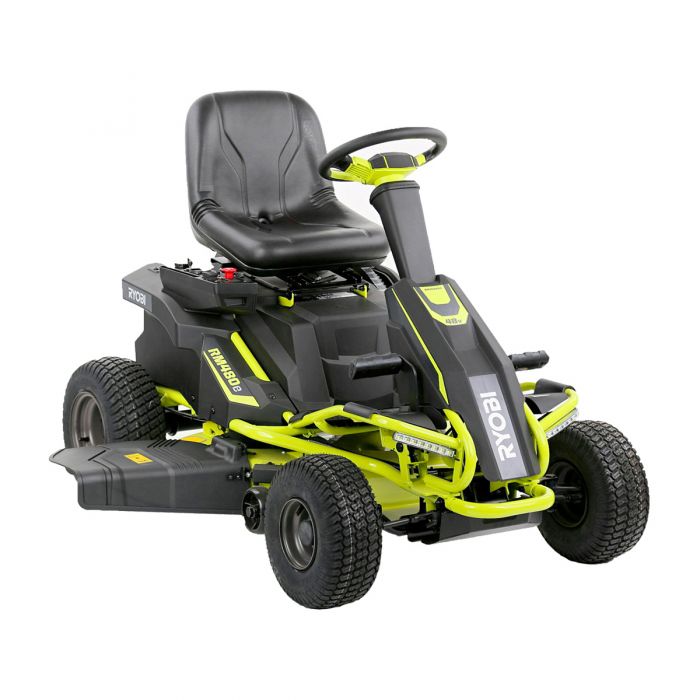
The Ryobi RM480e was one of the first mass-market, sub-$3,000 battery-powered riding lawn mowers in the United States, introduced through The Home Depot and quickly drawing favorable reviews from outlets such as Pro Tool Reviews, Today’s Mower, and Consumer Reports. The platform comprises three brushless direct-drive motors (one for the transaxle and two for the deck), a 48-volt battery pack assembled from four 12-volt sealed lead-acid batteries connected in series, a Delta-Q SC48 onboard charger, two deck motor controllers configured as master and slave, and a separate drive motor controller. While the design is mechanically simple in comparison to a gasoline tractor, the electrical system is sophisticated, and almost every recurring complaint owners report on lawn mower forums, on Reddit, and in Home Depot reviews traces back to one of those electronic subsystems or to the lead-acid battery pack itself.

This article examines the most frequently reported problems with the Ryobi RM480e, including its variants RM480ex and the RY48110, RY48111, and RY48112 model numbers, and provides detailed troubleshooting steps and solutions. It is written for owners who are willing to perform basic electrical diagnostics with a digital multimeter and who want to avoid the lengthy turnaround and high pickup-and-delivery fees that authorized service centers commonly charge for these mowers. Where a repair is unsafe to attempt at home, that is noted and professional service is recommended.
Table of Contents
Overview of the RM480e Platform and Its Variants
Before discussing failures, it is helpful to understand the differences across the RM480e family because problem prevalence is closely tied to the specific configuration owners purchased.
The RM480e (model RY48110) ships with four 12-volt, 75-amp-hour Leoch LPC12-75 sealed absorbed-glass-mat (AGM) lead-acid batteries, providing approximately 4,000 watt-hours of energy and roughly 2 hours of mowing runtime. The RM480ex (model RY48111) is functionally identical to the RM480e but ships with the larger 100-amp-hour Leoch LPC12-100 batteries, providing approximately 4,800 watt-hours and approximately 2.5 hours of runtime. The RY48112 is a variant covered under the same operator’s manual. All three variants use the same 38-inch deck, the same drive motor controller (commonly identified by part number 996508001), the same dual deck motor controllers (master and slave), and the same Delta-Q SC48 charger with a charger receptacle commonly identified by part number 996515001. Detailed specifications for the entire family are documented in the official RM480ex series operator’s manual.
Production has spanned approximately 2017 through the present. Owners of pre-2019 mowers should be aware of a documented design quirk in the older Delta-Q SC48 charger firmware: when the charger is left connected during long-term storage, it only initiates a top-up charge once every 30 days. An engineer at Delta-Q Technologies confirmed this behavior to a forum user on the Lawn Mower Forum thread that has accumulated more than 14 pages of owner reports. Owners of newer post-2019 units appear to receive a different charge profile, although Ryobi has not published a service bulletin formally describing the change.
Across all variants the most commonly reported failure modes, in approximate order of frequency, are battery degradation due to series-string imbalance, drive motor controller failure (often reported as “mower lurches forward an inch and stops”), charger receptacle and lockout faults, deck motor electronic-speed-controller failure, and intermittent contactor or solenoid clicking under the seat.
Ryobi RM480e Battery and Charging Problems
The four-battery, 48-volt series string is the single most common source of complaints on the RM480e. Owners on Reddit, the Lawn Mower Forum, the DIY Solar Power Forum, and the Tools in Action forum consistently describe degraded runtime, refusal to charge, charger fault flashes, and complete pack death in the second through fifth year of ownership. User reviews suggest replacement intervals anywhere in the range of 1 to 4 years, and a full replacement of all four Leoch batteries can approach 25 percent of the price of a new mower.
Symptoms
Battery and charging problems present in several distinct but related ways. Owners report the gauge displaying full charge yet the mower shutting down within minutes of mowing thick grass; the gauge cycling between 70 percent and 100 percent immediately after a full overnight charge; the charger displaying two flashing red LEDs rather than steady green; the charger displaying a “battery voltage failure” or fault message; the mower stopping and beeping repeatedly with a request to “return and charge” while batteries are nominally full; and, in the most severe cases, the mower failing to power on at all after winter storage despite having been left plugged in.
Causes
The root cause in nearly every case is the series-charging architecture. Because four 12-volt batteries are charged as a single 48-volt string, any internal capacity mismatch among the four cells causes the strongest battery to be progressively overcharged while the weakest battery is progressively undercharged. As one long-term owner observed after years of troubleshooting, series charging of mismatched batteries causes good batteries to be overcharged while bad batteries are undercharged, with the problem worsening over time. Sulfated batteries climb quickly to nominal voltage but cannot deliver current under load, which the gauge incorrectly interprets as a full charge.
Secondary causes include a disconnected or faulty battery temperature sensor (sometimes called the heat sensor lead) clipped to the positive battery cable; this sensor must be properly attached for the charger to allow charging to begin. Corroded or loose battery terminals are another frequent cause, particularly on mowers stored in humid garages. Charger receptacle failures, in which the receptacle’s internal interlock contacts oxidize, prevent the charger from energizing the pack even though the charger LED appears normal until plugged in.
The pre-2019 Delta-Q SC48 charger’s 30-day top-up interval is itself a contributing cause of premature battery death during storage. Sulfated batteries left without a maintenance charge for 30 days never fully recover.
Troubleshooting Steps
Begin by removing the seat and battery cover and inspecting all four 12-volt batteries with a digital multimeter set to direct-current volts. With the charger disconnected and the key off, each battery should rest at approximately 12.7 to 13.2 volts after a full charge and at least 12.4 volts after sitting overnight. A reading below 12.0 volts indicates a sulfated or failing battery. The total pack voltage measured at the main fuse should be approximately 50.8 to 53.2 volts.
Next, inspect the temperature sensor lead. It is a small thermistor clipped to the positive battery post or attached along the positive cable. If it has fallen off or its connector has separated, reattach it and retest the charger. Multiple owners have reported that simply reseating this sensor resolved a non-charging condition.
Inspect the charger receptacle. Verify that the receptacle’s three pins are clean, that the green status LED illuminates when the charger plug is inserted, and that no plastic of the receptacle is melted or cracked. Check the in-line 5-amp control fuse located near the receptacle and the main 125-amp battery fuse located on top of the battery tray.
If the charger displays two red flashes, consult the LED indicator chart in the operator’s manual. Two flashes most commonly indicate a battery pack connection problem or a battery temperature outside the allowable range. Allow the pack to cool for 15 minutes and try again. If the fault persists after 15 minutes and the pack is at room temperature, the next likely culprit is a deeply discharged battery that the smart charger will not recognize.
Finally, charge each of the four batteries individually with an external 12-volt automotive smart charger to bring them to a balanced state. Reading and recording each battery’s voltage after a 24-hour rest will reveal which cells are no longer holding charge.
Solutions
If one battery is significantly weaker than the others, replace the entire set of four. Mixing old and new batteries in a series string causes the new batteries to be dragged down by the old ones almost immediately, and Ryobi specifically warns in the operator’s manual against mixing makes or sizes. The factory-specified replacement is the Leoch LPC12-75 for the RM480e or LPC12-100 for the RM480ex, sold through The Home Depot. Many owners have successfully substituted MightyMax AGM batteries of equivalent rating; these are widely reported to provide comparable service life at a lower price.
For owners willing to perform a more involved upgrade, a growing community has documented conversion to lithium iron phosphate (LiFePO4) batteries, which weigh approximately one-third as much, last 5 to 10 times as long, and provide noticeably extended runtime. Owners considering this conversion should be aware of three pitfalls: the stock charger’s lead-acid charging profile may overcharge LiFePO4 cells unless replaced with a 58.4-volt or 54.6-volt LiFePO4-specific charger; the deck motor controllers are sensitive to in-rush current and have been reported to fail when LiFePO4 batteries are connected without an in-rush current limiter or precharge resistor; and the stock fuel gauge no longer accurately reads state of charge and must be supplemented with an aftermarket coulomb-counting battery monitor.
Owners in long-term storage situations should disconnect the four batteries from the harness and place each one on an individual maintenance charger over winter. Several long-term owners have reported complete elimination of charger and runtime issues after rewiring their mowers for independent 12-volt charging using a four-bank automotive battery charger.
Ryobi RM480e Drive and Mobility Problems
The single most frequently discussed RM480e problem on the internet, by a substantial margin, is the mower refusing to move while every other system continues to function normally. The dedicated Lawn Mower Forum thread on the RM480e drive failure has been active continuously since 2020 and has accumulated more than 14 pages of reports, making it the most comprehensive owner-reported diagnostic record for this issue.
Symptoms
Owners report a remarkably consistent pattern of symptoms. Typical descriptions include: the mower lurches forward 1 to 6 inches when the accelerator pedal is depressed and then stops dead; the mower will not move forward or reverse but the blades engage normally and the headlights work; toggling the key off and on resets the mower temporarily but the failure recurs within seconds to minutes; the mower works perfectly in cold weather (below approximately 60 degrees Fahrenheit) but fails when ambient temperature climbs; the mower beeps three times indicating a circuit disconnection; the mower works only if the accelerator is depressed extremely lightly; and a digital “H” appears on the gauge before the mower stops.
Causes
The dominant cause is failure of the drive motor controller, part number 996508001. This controller is a sealed potted assembly: owners who have dissected failed units have reported that the entire electronics board is encapsulated in a hardened heat-conducting compound, making the unit non-serviceable. Owners have reported white smoke and black liquefied potting compound oozing from the controller housing in catastrophic failure cases, indicating thermal breakdown of the internal MOSFETs and capacitors.
Multiple owners have reported being on their second or third drive motor controller within 5 years of purchase. One representative forum post described being on a third drive motor controller within 3 years and noted that the volume of similar reports across the community suggests this is a known design weakness rather than isolated bad luck.
Secondary causes include failure of the accelerator pedal transducer (a Hall-effect throttle position sensor), failure of one of three Hall sensors mounted on a small printed circuit board inside the brushless drive motor (functionally equivalent to the brushes in a brushed motor), a blown 125-amp main battery fuse located on top of the battery tray, a blown 5-amp control fuse located near the 12-volt direct-current converter, a faulty seat switch, a parking brake interlock not fully released, or the forward-reverse rocker switch which has been described by multiple owners as unreliable on these mowers.
In a small number of cases, weak batteries can cause the same symptom. When the controller detects voltage sag below a safe threshold during current draw, it shuts off the drive output to protect itself.
Troubleshooting Steps
Verify the obvious safety interlocks first. The start key must be in the ON position, the parking brake must be released, the direction control switch must be in either forward or reverse rather than neutral, the brake pedal must not be depressed, the operator must be seated, and the charger must be unplugged from the receptacle. The charger lockout circuit prevents drive when the charger is connected, even if the charger itself is not energized.
Check both fuses. The 5-amp fuse located near the 12-volt direct-current converter under the right rear tire is accessible by removing the rear panel. Multiple owners have reported that simply pulling and reseating this fuse resolves intermittent drive failure. The 125-amp main battery fuse on top of the battery tray will be obviously open if blown.
Test the drive motor controller for a short circuit. Disconnect the controller power leads. Set the multimeter to resistance mode. Measure resistance between the red power input cable and the black power input cable. The nominal reading should be 750 kilohms or higher, or read as “open.” A reading near zero ohms indicates a shorted controller that must be replaced. Next, check continuity between any two of the heavy three-phase output terminals (yellow, green, blue). The reading should be open or several megohms. Continuity between phases also indicates a shorted controller.
Test the accelerator pedal transducer by measuring the signal voltage on the small connector running from the pedal assembly. With the key on, brake released, and pedal at rest, the signal should be at the minimum value specified in the service literature. Pressing the pedal should produce a smoothly varying voltage. A flat or noisy reading indicates a failed transducer.
Test the drive motor itself. With the controller disconnected from the motor, manually rotate the rear wheels with the parking brake released. The motor should rotate freely with even resistance. A grinding feel or visibly damaged Hall sensor PCB indicates motor damage.
Solutions
For a confirmed shorted or failed drive motor controller, replace part number 996508001. Genuine Ryobi controllers have ranged from approximately $275 to $400, with availability through Ryobi parts ordering, eBay, and small-engine parts dealers. Replacement is mechanical and straightforward, requiring removal of the rear panel and disconnection of three power cables and one signal cable.
For a failed accelerator transducer, the part is widely available for approximately $120. Be aware that Ryobi customer service has occasionally shipped a blade motor controller in error when an accelerator transducer was requested; verify the part number before installation.
For a failed drive motor, owners have reported with frustration that Ryobi does not sell the motor as a separate part and instead sells the motor and transaxle as a single assembly, which can exceed $800. In this case the cost of repair frequently approaches the cost of a new mower of similar specification. A small number of owners have successfully sourced bare brushless motor replacements from third-party suppliers and reconfigured the controller mapping using open-source VESC tools, but this is an advanced modification and is not supported by Ryobi.
For a failed seat switch, replacement switches are inexpensive and accessible by lifting the seat. Several owners have reported intermittent drive failure that was resolved by re-crimping a single wire that had pulled out of the seat switch connector.
When the failure is intermittent and temperature-dependent, allow the mower to cool, retry, and consider preemptively replacing the controller before complete failure occurs in the middle of mowing.
Ryobi RM480e Blade and Deck Motor Issues
The RM480e uses two independent brushless deck motors, each driving its own 19-inch blade. Power and commutation signals to these motors are managed by a pair of deck motor controllers wired in a master-slave configuration. The master controller communicates with the operator’s blade engagement switch and supervises the slave controller; the controllers must both be functional for either blade to operate.
Symptoms
Common reports include: blades engage briefly for approximately 3 seconds and then shut off, with one or both blades not turning at all; one blade rotates while the other does not, even when their motor connectors are swapped; blades engage but shut off whenever the mower attempts to climb a slight incline; blades cause the entire mower to enter a limp state, slowing down or refusing to drive; and a constant beep accompanying any blade engagement attempt.
Causes
The most common cause is a failure of one of the two deck motor electronic speed controllers. The slave controller often fails first, sometimes immediately after a battery swap or LiFePO4 conversion that introduces voltage transients during connection. The master and slave communicate over a shared signal line; if either fails, both blades become inoperable because the master will not enable output without confirmation from the slave.
Secondary causes include a failed deck motor (often diagnosed by manually rotating the blade and feeling abnormal resistance, tightness, or a clicking sound from the motor bearings or Hall sensors); a damaged wiring harness between the controller and the motor; a faulty blade engagement switch (the pull-up knob on the dashboard); a failed safety interlock such as the seat switch (which disables blades when the operator is not seated); and worn, bent, or unbalanced blades that draw excessive current and cause the controller to enter overcurrent shutdown.
Troubleshooting Steps
Begin by removing the deck for safe access. Set the direction control switch to neutral, lower the blade engagement knob, remove the start key, and engage the parking brake. With the deck removed, attempt to rotate each blade by hand with the batteries disconnected. The blades should rotate smoothly through a full 360 degrees. A blade that rotates with audible clicking or significantly higher resistance than the other indicates a failed motor or a bent shaft.
Swap the motor connectors at the controller. If the previously non-functional motor now runs and the previously functional motor stops, the failure is in the controller, not the motor. If the failure follows the motor, the motor itself is the problem.
Inspect the wiring harness for chafing, rodent damage, or pinched insulation, paying particular attention to the harness routing along the deck pivot points where movement during deck height adjustment can wear through insulation.
Test the seat switch with a multimeter set to continuity mode. The switch should close when the seat is occupied. A constant beep when blades are engaged usually indicates the seat switch or another interlock is open.
Solutions
A failed deck motor controller is replaceable as an assembly, although Ryobi treats the master and slave as distinct part numbers. When ordering, confirm whether the master or slave is required because they are not interchangeable. As an alternative, advanced owners have replaced both stock deck motor controllers with a pair of aftermarket vehicle electronic speed controllers configured using open-source firmware. This conversion bypasses the master-slave dependency and several built-in safety features such as the seat-switch blade interlock and the blade slow-down button. This modification involves working with capacitors that can retain charge with the ignition off and is suitable only for owners who fully understand the safety implications.
A failed deck motor must be replaced as an assembly. Replacement involves removing the deck, disconnecting the motor harness, and unbolting the motor from the deck shell. Use only genuine Ryobi blade bolts when reinstalling blades, and replace blades as a balanced pair rather than individually to prevent vibration. Ryobi specifies the ACRM002 mulching and side-discharge blade pair and the ACRM003 bagging blade pair, both available through The Home Depot.
If a blade is bent, severely worn, or missing the locking nut, the resulting imbalance can damage the motor shaft and the deck bearings. Replace blades as soon as significant wear is detected.
Ryobi RM480e Electrical and Ignition Problems
Beyond drive and deck systems, the RM480e has a number of low-voltage electrical subsystems that can fail and produce confusing symptoms. These include the keyed ignition switch, the safety interlock harness, the headlights, the cruise control circuit, the 12-volt direct-current converter that powers all accessories, and the wiring harness throughout the mower.
Symptoms
Reports include: complete loss of power on the dashboard with the key in the ON position despite a fully charged pack; intermittent flashing of the battery gauge or a flashing “H” on the digital readout; the mower cycling on and off every few seconds; the headlights flickering or one headlight working while the other does not; the USB charging port being non-functional; the cruise control failing to engage; and the mower starting and immediately turning off as soon as the operator releases the key from the START position.
Causes
The root cause of complete dashboard blackout is most often a blown 5-amp control fuse. This fuse protects the 12-volt accessory circuit derived from the 48-volt pack via the dedicated direct-current converter. If the converter itself has failed, no 12-volt accessory power will be available and the dashboard will go dark.
Flashing gauges and “H” displays usually indicate a fault detected by the controller and signaled to the dashboard. The “H” notation, although not formally documented in the user manual, has been informally suggested by forum participants to represent a heat or high-voltage fault. The controller has a temperature sensor on its heatsink and may derate or shut down output when the heatsink exceeds approximately 80 degrees Celsius.
A failing keyed ignition switch can cause intermittent power dropouts that mimic battery or controller failure. The keyed switch carries low signal current rather than full pack current, so symptoms appear electronic rather than thermal.
Headlight flicker is most commonly caused by a wire that was not fully crimped to its pin at the connector during factory assembly. Owners have reported correcting flickering headlights simply by re-crimping the connector pin.
Troubleshooting Steps
If the dashboard is completely dark, first verify that the main 125-amp battery fuse is intact. With the fuse removed, measure resistance across the fuse element; a good fuse reads near zero ohms. Next, check the 5-amp control fuse near the 12-volt converter under the right rear panel. If both fuses are intact, measure the output of the 12-volt converter at its output terminals. A healthy converter should output between 12 and 14 volts direct current. No output indicates a failed converter, which can be replaced relatively inexpensively (some owners have substituted a generic 48-volt-to-12-volt direct-current step-down converter with a comparable amperage rating).
For a flashing gauge, attempt a controlled reset by turning the key off, waiting 30 seconds, and turning the key back on. If the fault clears, monitor the mower for recurrence and note the conditions under which it returns (heat, slope, blade load).
For ignition switch problems, remove the front console (typically four T30 Torx screws) and inspect the back of the switch for melted plastic, loose terminals, or arcing. The switch is a standard automotive-style assembly and inexpensive to replace.
Solutions
Replace blown fuses with fuses of the exact same rating; never substitute a higher-amperage fuse, as the wiring harness is sized to the original protective rating. After replacing a 5-amp fuse, mow for a short period and verify the fuse does not blow again. A repeated blown fuse indicates a short circuit elsewhere in the 12-volt system that must be located and repaired.
For a failed 12-volt direct-current converter, replacement is straightforward: disconnect the input and output terminals and substitute a converter of identical voltage and amperage rating. Several owners have noted that aftermarket converters from the recreational vehicle and golf cart aftermarket are less expensive and more robust than the original.
For a failed keyed switch, replacement takes approximately 15 minutes with the front console removed.
Ryobi RM480e Control Module and Relay Failures
The 48-volt high-current circuit is switched on and off by a heavy-duty direct-current contactor, identified on its case as ZLJ-200A. This is functionally analogous to a starter solenoid on a gasoline mower but rated for continuous direct current at 48 volts and 200 amperes. The contactor closes when the key is turned and the safety interlocks are satisfied, allowing battery current to reach the drive motor controller and deck motor controllers.
Symptoms
Reports include: a loud, audible click from beneath the seat when the key is turned to the ON position followed by no further activity; repeated clicking that does not result in motor activation; a single click followed by the mower lurching forward 1 inch and stopping; clicking that occurs but no power reaching the motors; and the contactor remaining mechanically engaged with no power output.
Causes
The ZLJ-200A is a sealed mechanical contactor whose internal contacts can pit, weld, or burn after thousands of cycles. When the contacts pit, voltage drop across the contactor increases under load, the controller detects undervoltage, and the controller cuts output. The contactor itself can also fail in the open or closed position. A contactor that clicks but does not pass current has either welded auxiliary contacts or pitted main contacts.
Secondary causes of clicking-related symptoms include a weak battery pack that drops voltage during the in-rush current of contactor closure, causing the controller to immediately reset; corroded or loose terminals on the contactor’s high-current studs; and a failure in the low-voltage coil drive circuit that prevents reliable contactor closure.
The drive motor controller and the deck motor controllers, although not technically relays, also fall under the broader category of control modules. Their failure modes have been described in detail above.
Troubleshooting Steps
Locate the ZLJ-200A contactor under the seat or rear panel. With the key off and the parking brake set, visually inspect the contactor for burn marks, melted plastic, or oxidized terminals.
With a multimeter set to direct-current volts, measure across the two large input and output studs of the contactor. With the key off the reading should be the full pack voltage of approximately 51 volts (because the controller side has discharged to zero through internal bleed resistors). With the key on, the reading should drop to less than 0.2 volts; a higher reading indicates a high-resistance contact and incipient failure.
Listen carefully for a single, clean click when the key is turned. Multiple clicks, chattering, or a faint click indicate marginal coil power, which can be caused by low pack voltage, a failing keyed switch, or an open safety interlock.
Solutions
Replace the ZLJ-200A contactor if voltage drop testing confirms degraded contacts. Generic 48-volt 200-amp direct-current contactors are widely available through golf cart parts suppliers and electric vehicle parts suppliers; the ZLJ-200A and equivalents from Albright, White-Rodgers, and Kilovac are functionally interchangeable when matched on coil voltage, contact rating, and mounting pattern.
For the soft-start in-rush problem that affects LiFePO4 conversions, install a precharge resistor or a dedicated in-rush current limiter relay between the battery pack and the controller. Aftermarket prebuilt automatic in-rush resistor-relay surge protectors specifically designed for the RM480e LiFePO4 conversion are available from small specialty suppliers in the electric mower modification community.
Ryobi RM480e Maintenance-Related Failures
A meaningful fraction of RM480e failures are not strictly electronic in origin but result from omitted or incorrect maintenance. Because the mower has no engine oil, no spark plug, no air filter, no belts, and no fuel filter, owners often assume there is nothing to maintain. The official maintenance schedule in the operator’s manual specifies otherwise.
Symptoms
Maintenance-related symptoms include uneven cutting from one side of the deck to the other, excessive vibration when blades engage, low tire pressure causing the deck to scalp on one side, the parking brake failing to engage or hold, premature blade wear, debris accumulation on the deck and inside the motor housings causing thermal cutoffs, corroded battery terminals, and reduced battery runtime.
Causes
The blade and deck motor system shares many of the wear characteristics of a conventional gasoline mower deck. Blades dull, become bent on impact with rocks or roots, and lose their balance. Deck level adjustments shift over time as the deck pivots, hitch pins wear, and tires lose air. The parking brake is a mechanical drum-style assembly that can fall out of adjustment.
Battery terminal corrosion is a slow process that progresses faster in humid climates. Corroded terminals introduce resistance, which causes voltage drop under load and can cause the same symptoms as a degraded battery. Debris allowed to accumulate on top of the battery tray can short low-voltage signal wires.
Troubleshooting Steps
Before each use, the operator’s manual specifies that the operator should check brake operation, check tire pressure, verify the safety interlock system, check for loose fasteners, remove debris from the mower, adjust the seat, and verify the battery charge level.
Every 25 hours of operation, the operator should check and replace blades as needed and clean the battery terminals.
Every 50 hours of operation, the operator should lubricate mower pivot points, the front axle pivot and axle spindles, the front axle wheel bushings, and the deck pivot points.
Before storage and yearly, all of the above checks should be performed plus a full charge of the battery pack and a thorough cleaning of all electrical connections.
Solutions
Sharpen or replace the blades as soon as cutting performance degrades. Use only Ryobi-specified blades (ACRM002 for mulching and side discharge, ACRM003 for bagging). Always replace blades as a pair to maintain deck balance.
Verify that all four tires are inflated to the pressure specified on the tire sidewall. Uneven tire pressure produces uneven cutting and accelerates deck pivot wear.
Adjust the parking brake by placing the direction control switch in neutral, holding the brake pedal down, lifting the parking brake lever fully up, releasing the brake pedal, and then releasing the parking brake lever. If the brake still does not hold, inspect the brake cable and brake mechanism for damaged or missing components.
Clean battery terminals using a battery terminal brush and a baking-soda-and-water solution. After drying, apply a thin coat of dielectric grease or terminal protectant. Tighten all terminals to the specification given in the operator’s manual.
Note that Ryobi specifically warns against using water to wash beneath the deck or anywhere near the electrical system. The recommended cleaning method is compressed air. Long-term owners commonly use a compressor to blow grass and dirt off the entire mower from top to bottom after each mowing session.
Preventive Maintenance and Recommended Servicing Schedule
A disciplined preventive maintenance program is the single most effective way to extend RM480e service life and avoid the high-cost repairs documented above. The following recommendations consolidate the operator’s manual schedule with the practical experience reported by long-term owners.
Battery Care and Charging Practices
The lead-acid battery pack is the most expensive consumable on the mower. To maximize service life:
Charge the mower immediately after each use. Lead-acid batteries are damaged by sitting in a discharged state, and the smart charger will return to a maintenance mode automatically once the pack is full. Avoid running the pack below 20 percent state of charge whenever possible, as deep discharge cycles measurably shorten lead-acid life.
Verify that the temperature sensor lead is securely attached to the positive battery cable. A loose sensor will prevent proper charging.
Inspect the four batteries individually at least once per season using a multimeter. Any battery whose resting voltage falls more than 0.3 volts below the others is showing early signs of capacity loss and should be considered for replacement before it drags down the rest of the pack.
For long-term storage, particularly through a northern winter, owners with pre-2019 mowers should not rely on the stock charger’s storage maintenance behavior. Either disconnect the batteries and place each on an individual maintenance charger, or install a 48-volt battery maintainer such as a PulseTech-style desulfation system, which several long-term owners have credited with extending pack service life by a factor of 2 to 3.
If converting to LiFePO4, replace the stock charger with a charger matched to the LiFePO4 chemistry (typically 54.6 volts at 10 amperes for a 48-volt nominal pack), install an in-rush current limiter, and install an aftermarket battery monitor since the factory gauge will no longer read accurately.
Cleaning Electrical Connections
Once per season, remove the seat and battery cover and inspect every electrical connection. Apply dielectric grease to battery terminals and to the high-current studs on the ZLJ-200A contactor. Inspect the charger receptacle for oxidation; a small amount of contact cleaner applied with a cotton swab restores conductivity.
Inspect the wiring harness where it crosses pivot points (deck height adjustment, front axle, steering column) for chafing or pinching. Re-route or wrap any abraded wiring with self-fusing silicone tape before bare conductors short to chassis.
Inspecting Wiring and Fuses
The 5-amp control fuse and the 125-amp main fuse should both be visually inspected before each mowing season. Carry a spare of each in the under-seat storage area; both are inexpensive and far more available than a controller. Inspect the fuse holders for heat discoloration, which indicates loose contacts and pending failure.
Inspect all in-line connectors for the seat switch, the brake interlock switch, the parking brake interlock switch, and the charger lockout switch. These low-current switches are inexpensive to replace and account for a disproportionate share of “mower will not move” complaints.
Maintaining Deck Motors and Blades
After every 25 hours of operation or at minimum once per season, remove the deck and inspect the blades. Sharpen them on a balanced sharpener or replace them. Verify the blade bolt torque against the operator’s manual specification. Inspect the underside of the deck for grass buildup and clear it with compressed air or a plastic scraper; never use water.
Inspect each deck motor for loose mounting bolts, harness chafing, and signs of overheating such as discolored housings. Manually rotate each blade with the batteries disconnected and verify smooth, even rotation.
Seasonal Storage Practices
Before storage, charge the pack fully, clean the deck and chassis with compressed air, lubricate the pivot points, and store the mower on a level surface in a dry location. Protect the mower from temperature extremes; lead-acid battery service life decreases significantly when stored at temperatures above 90 degrees Fahrenheit or below 32 degrees Fahrenheit.
If storing the mower outdoors is unavoidable, use a breathable mower cover rather than a plastic tarp, which traps condensation. Cover the charger receptacle with its rubber cap to keep moisture out of the contacts.
When returning the mower to service in spring, perform every item on the “before each use” checklist plus a full battery diagnostic. Many of the catastrophic spring failures documented on owner forums could have been prevented by recognizing battery degradation before the controller was stressed by the resulting voltage sag.
When to Seek Professional Service
Several scenarios warrant professional service rather than home repair. Authorized service centers can be located through the official Ryobi parts and service portal. Recommendations for professional service include:
Any time the high-current 48-volt system shows visible damage such as melted insulation, smoke, or arcing. The energy stored in a fully charged 48-volt 100-amp-hour pack is comparable to a small car battery and a short circuit can produce a dangerous fault current.
Any time the charger or charger receptacle shows signs of internal arcing or overheating. The charger contains line-voltage components and is not user-serviceable.
When a controller has failed in a smoking or potting-leakage manner, both because the failure may have damaged adjacent components and because the failure may indicate a wiring fault that must be located before the replacement controller is installed.
When the mower is still under the original 3-year limited warranty. Many owners have reported that Ryobi customer service, although difficult to reach, will often ship a replacement controller directly to a knowledgeable owner rather than requiring a service-center visit. Calling Ryobi customer support at the number printed in the operator’s manual is always the recommended first step for any in-warranty issue.
Conclusion
The Ryobi RM480e remains, by virtue of price and feature set, one of the most accessible electric riding mowers available to American homeowners. Its mechanical design is straightforward and its blades, tires, and brake system are no more demanding to maintain than any conventional riding mower. Its electrical systems, however, suffer from several recurring weaknesses: a series-connected lead-acid battery pack that develops imbalance over time and is sensitive to long-term storage; a drive motor controller potted in a heat-conductive compound that has demonstrated a tendency to fail thermally; deck motor controllers configured in a master-slave architecture that fails as a unit; and a charger receptacle and lockout circuit that is the single most common point of mysterious “no power” failures.
Owners who understand these weaknesses, perform the modest preventive maintenance the operator’s manual specifies, charge the pack consistently, watch for early signs of battery imbalance, and keep a digital multimeter in the garage can resolve the majority of failures themselves at component costs that are typically a fraction of a service-center repair. Owners who are willing to depart from the original specification, particularly through a LiFePO4 battery upgrade with an appropriate charger and in-rush current limiter, frequently report that the RM480e delivers years of additional reliable service well beyond what the original lead-acid pack permits.
Either approach, attentive maintenance of the original system or a measured upgrade of its weakest components, is preferable to abandoning a mower that, when functioning correctly, remains an exceptionally quiet, clean, and capable machine for residential mowing.