
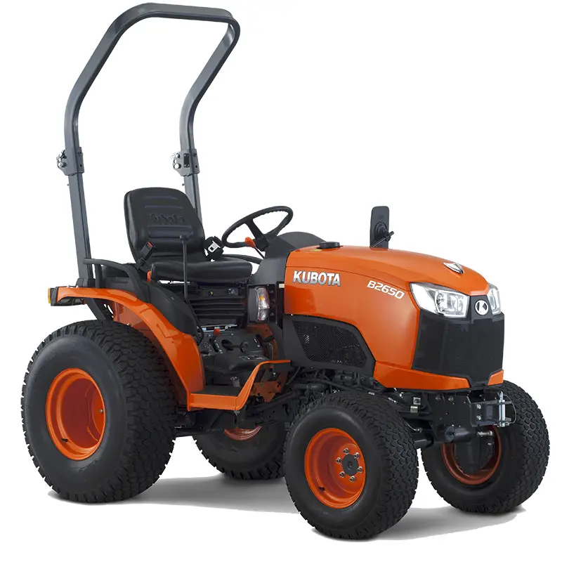
The Kubota B2650 is a sub-compact utility tractor that occupied an important place in Kubota’s B-50 series lineup from approximately 2014 through 2020. Built around the company’s well-regarded D1305 three-cylinder diesel engine and offered in two principal configurations—the open-station B2650HSD with a foldable two-post Roll-Over Protective Structure (ROPS) and the cab-equipped B2650HSDC with factory air conditioning and heat—the B2650 became a popular choice for hobby farmers, rural property owners, landscapers, snow-removal contractors, equine facility managers, and small-acreage producers across the United States. Rated at 26 gross horsepower with approximately 19.5 power take-off (PTO) horsepower, paired with a three-range hydrostatic transmission (HST), four-wheel drive, wet-disc brakes, and a power-steering system fed by an open-center hydraulic circuit, the B2650 was marketed as the heavier, more capable counterpart to the smaller B2601 and was typically equipped with the LA534 front-end loader and optional BH77 backhoe, as detailed in the official Kubota B2650 and B3350 brochure.

Despite its strong reputation for reliability, the Kubota B2650 has accumulated a documented set of recurring problems that owners encounter as the platform matures and accumulates hours. The single most-discussed Kubota B2650 problem across forums such as TractorByNet, OrangeTractorTalks, and the r/kubota subreddit is intermittent stalling and no-start conditions traced to the hydrostatic transmission pedal safety switch. Other recurring issues include hydraulic anomalies on the loader and three-point hitch circuit, overheating during prolonged heavy work on slopes, loader-arm flex, factory-routed loader hoses that chafe against frame members, a cab-specific design conflict in which the rear three-point hitch can strike the rear cab glass, weak charging output from the original-equipment dynamo on ROPS units, and a variety of fuel-system, electrical, and maintenance-related concerns common to small Tier-IV diesel tractors.
This Kubota B2650 troubleshooting guide presents a structured, U.S.-focused reference for owners, dealers, and technicians. Each major problem category is treated in turn with symptoms, causes, troubleshooting steps, and solutions, supplemented by part numbers, fluid capacities, and torque guidance drawn from the Kubota workshop manual, dealer parts catalogs, owner manuals, and dealer service experience. Variant-specific differences between the B2650HSD and B2650HSDC, as well as between earlier and later production units, are noted where they are relevant. A dedicated preventive-maintenance section and direct quotations from owner forums are included to ground the guidance in real-world operator experience.
Engine Starting Problems
Symptoms
Owners report several distinct starting-related symptoms on the B2650. The most common is a tractor that cranks but will not catch in cool or cold weather despite an apparent glow-plug warm-up cycle. A second pattern is a tractor that produces no crank at all—dash lights illuminate, but turning the key produces no clicking, no starter engagement, and no fuel-solenoid activity. A third pattern is intermittent: the tractor will start one day and refuse to start the next, with the operator often forced to rock the HST treadle pedal back and forth several times before the engine will turn over. Excess white smoke during attempted starts, blown 5-amp Operator Presence Control (OPC) fuses, and engines that start briefly and then stall when the operator presses the HST pedal also fall under this heading.
Causes
Hard cold-starting on the Kubota B2650 most often traces to the glow-plug system. The D1305 uses three glow plugs—one per cylinder—rated at approximately 1 ohm each with a combined parallel resistance near 0.33 ohms. A single open or damaged plug can disrupt cold ignition. Operator error compounds the issue: unlike many automotive diesels, the B2650 glow-plug circuit is energized only while the key is held in the spring-loaded preheat position; releasing the key prematurely terminates the heating cycle. Owners who hold the key in the preheat position for excessively long durations (one to two minutes, as some forum posts admit) can damage the glow plugs themselves or burn out the 5-amp glow-plug fuse, leaving the engine essentially without cold-start support.
No-crank conditions almost always trace to the safety-interlock system, which wires the seat switch, the HST pedal neutral switch, the PTO neutral switch, and the range-shift neutral switch in series with the starter relay. If any switch is open, the starter circuit is dead. A blown 5-amp OPC fuse, located in the auxiliary fuse box near the battery on cab models, will produce identical symptoms.
Engines that start, run briefly, then die when the HST pedal is pressed are almost always indicating a failing HST treadle neutral switch or a failing seat switch. Air in the fuel system following filter service, water-contaminated diesel, a clogged primary fuel filter (Kubota part number 6A320-59930), failed fuel injectors, or a faulty fuel-shutoff solenoid can all also produce stall-after-start symptoms.
Troubleshooting Steps
Begin with the basics. Confirm battery voltage at 12.5 volts or higher with a digital multimeter, clean both terminals, and verify the main 40-amp slow-blow fuse at the front of the engine bay. On cab models, inspect the Littelfuse PAL-series fuses (PAL050BP red 50-amp female, PAL160BP yellow 60-amp male) located near the battery. Confirm that the OPC 5-amp fuse is intact; if it has blown, replace it but do not return the tractor to service before tracing the short.
For glow-plug diagnosis, disconnect the bus bar across the glow plugs and ohm each plug individually to ground. A reading near 1 ohm is normal; an open circuit indicates a failed plug. Test the glow-plug relay by listening for an audible click when the key is held in the preheat position, and verify 12 volts at the relay output terminal. Hold the preheat for three seconds above 30 degrees Fahrenheit, five seconds between 0 and 30 degrees, and eight to ten seconds in single digits, then release the key directly to the start position.
For no-crank or stall-on-pedal issues, locate the HST pedal neutral safety switch under the right floorboard, just forward of the hydraulic filter on the right-hand side of the transmission case. With the key in the on position, observe the switch plunger as the pedal is rocked. The plunger should depress fully when the pedal is centered. Spray the switch and its actuating loop liberally with electrical contact cleaner or a penetrating lubricant such as PB Blaster or CorrosionX. Cycle the pedal twenty or thirty times. If the symptom persists, unplug the connector and use a jumper across the two terminals to confirm whether the switch is the failure point. A jumper that allows the tractor to start and run normally confirms a bad HST pedal switch.
Air-bleed the fuel system after any filter service. Crack the bleed screw at the top of the fuel filter housing, then the bleed plugs at the injection pump in sequence, while operating the manual primer lever on the mechanical lift pump or while cranking the engine in short bursts, until clear, bubble-free diesel emerges.
Solutions
For damaged glow plugs, replace them as a complete set. Apply a small amount of anti-seize compound to the threads but not to the heating element, and torque to approximately 11 to 14 foot-pounds. Replace any blown 5-amp glow-plug fuse with the same rating; never substitute a higher-amperage fuse, since this can damage the relay or the wiring harness.
For a confirmed faulty HST pedal neutral safety switch, replacement is straightforward but physically tight on cab models. The dealer parts price is typically $20 to $50, and dealers commonly stock the part because of its high failure rate. After replacement, adjust the switch so that it is fully depressed only with the pedal in the true neutral position, and verify by attempting starts in forward, reverse, and neutral pedal positions. Multiple owners have reported that, in addition to fixing the no-start fault, switch replacement also resolved a related “creeping” complaint where the pedal would not return fully to neutral.
One TractorByNet user summarized the experience that hundreds of owners have replicated: “I called the Kubota dealer to get an appointment to get it fixed. I barely got the description of the problem out of my mouth when the service guy says ‘Bad HST pedal switch. I’ve got a box of them up here.'”
For persistent fuel-related no-start conditions, replace the primary fuel filter (Kubota 6A320-59930) and bleed the system. If hard starts persist after fuel-system service and after confirming healthy glow plugs and good cranking voltage, suspect injector wear or low compression, both of which require dealer-level diagnosis, as documented in this B2650 stalling and no-start TractorByNet thread.
Hydraulic System Failures
Symptoms
The most distinctive Kubota B2650 hydraulic complaint is a selective failure pattern: bucket curl continues to operate normally while loader lift, loader lower, three-point hitch raise and lower, and any third-function circuit cease responding. Other reported hydraulic symptoms include weak or jerky three-point hitch motion, hydraulic fluid leaks at quick-couplers and at the banjo fitting near the rear axle (a known warranty issue when curling the bucket), erratic loader-valve “stickiness” where small lever inputs produce large initial movements, and total fluid loss following a strike to the suction filter.
Causes
Selective failure of multiple hydraulic functions while one continues to work points to a clogged hydraulic return filter (Kubota HH670-37710, superseded by HH670-37712), low fluid level, a stuck control-valve spool, or a failed quick coupler. The B2650 carries two filters on the combined transmission and hydraulic case: a separate HST filter (HH660-36060) for the hydrostatic charge circuit and a hydraulic return filter for the implement circuit. Both must be serviced at the 200-hour interval; ignoring this schedule is the most common precipitating factor.
Bucket-curl-only operation typically indicates that flow is reaching the loader valve but is being blocked further down the parallel circuit, which serves the lift, three-point, and any auxiliary functions. A clogged return filter is the simplest and most common cause. Hose damage from a strike to the suction-side filter (mounted low on the right rear of the transmission case) can rapidly drain the case—one B2650 owner reported losing essentially the entire 4-gallon (15.1-liter) charge in minutes after a stump struck the suction filter.
The hydraulic leak near the rear axle when the bucket is curled is a documented warranty issue traced to an O-ring or crush washer at the banjo bolt fitting that connects power-beyond plumbing to the loader valve.
Troubleshooting Steps
First, check fluid level on the dipstick located behind the seat or under the rear deck depending on configuration. Bring the fluid to the cold full mark with Kubota Super UDT2; capacity is approximately 4.0 U.S. gallons (15.1 liters). Inspect both filters visually and replace both if their service interval has been exceeded or if they cannot be confirmed by date or hours. Pre-fill new filters with clean Super UDT2 to prevent dry-start damage to the pump.
Bleed the hydraulic system by operating each function through its full range ten times: loader raise/lower, bucket curl/dump, three-point hitch up/down, steering lock-to-lock, and any third-function circuit. Foaming in the reservoir is normal during bleed-down and will dissipate.
For the bucket-curl-only failure, inspect each quick coupler on the loader. Disconnect and reconnect each one with the engine off and the loader resting; the joystick may need to be cycled with the engine off to relieve trapped pressure, or a male flare fitting on the loader may need to be cracked open momentarily to vent stored pressure on disconnected loaders. A coupler that resists reconnection is almost certainly stuck under residual pressure.
For the rear-axle leak when curling, inspect the banjo fitting located near the loader-valve power-beyond connection. Tighten with an 11/16-inch wrench gently if loose, and replace the O-ring (typically two different sizes are used, one at the bolt head and one at the housing flange) if the leak persists. The dealer fix is normally covered under warranty.
Solutions
Replace both hydraulic filters as a paired service item at 200-hour intervals. Confirm O-rings and gaskets seat properly, hand-tighten plus three-quarters of a turn after gasket contact, and torque drain plugs to approximately 50 foot-pounds for 12 millimeter bosses. Refill with 4.0 U.S. gallons of Super UDT2; do not substitute generic universal tractor transmission oil unless the substitute meets Kubota’s UDT or Super UDT specifications, since seal compatibility and HST charge-pressure performance are formulation-dependent.
For sticky loader valves, several owners report success treating the valve housing externally with a corrosion-inhibiting penetrant such as Boeshield T-9 or Fluid Film. Allow the lever and spools to cycle through a full range of motion ten or fifteen times before re-evaluating.
If a hose or fitting is damaged, replace with OEM components. Hose replacement on the LA534 loader runs approximately $100 to $200 per hose at dealer pricing, and chafing-related failures on tractors still under warranty should be brought to the dealer’s attention since the routing pattern is a known factory weakness.
Overheating Issues
Symptoms
Owners report a characteristic overheating signature on the B2650: normal operation in flat work, with the temperature gauge climbing into the upper range or triggering the high-temperature warning after twenty to thirty minutes of heavy PTO work, particularly on slopes or in tall, dense vegetation. The temperature usually returns to normal during a brief idle cool-down. Steam from the radiator, audible coolant boiling, and visible loss of coolant from the overflow bottle are more advanced symptoms.
Causes
The single most common cause is debris accumulation in the radiator core and on the front-mounted air-intake screen. The cooling fan draws air through the screen, and chaff, grass clippings, dust, and animal hair pack the fins quickly, especially during bush-hogging and brush-cutting operations. Cooling-system industry data attributes approximately 35 percent of small-tractor overheating cases to fin blockage. A weak or failed thermostat (which should begin opening near 160 degrees Fahrenheit and be fully open by 185 degrees Fahrenheit) is the second-most-common cause. Low coolant from a slow leak at a hose, the water-pump weep hole, a failed radiator cap, or the thermostat housing rounds out the principal causes. Continuous heavy PTO loading on inclines, where reduced airflow combines with peak engine load, accelerates symptom onset on the B2650 specifically because the D1305 in this chassis runs near its design heat-rejection limit during sustained 26-horsepower output.
Troubleshooting Steps
With the engine cool, open the hood and inspect the radiator core from both sides. Use compressed air (regulated to 30 to 40 pounds per square inch to avoid bending fins) blown from the engine side outward through the core. Inspect the front intake screen and the small condenser of the air-conditioning system on cab models, which sits ahead of the radiator and clogs first.
Check coolant level at the overflow bottle and at the radiator filler with the engine cold; the system holds approximately 4.5 U.S. quarts (4.3 liters) of 50/50 long-life ethylene glycol. Inspect the radiator cap rubber seal and pressure rating (typically 0.9 bar/13 psi for B-series tractors); replace if seal is hardened or cracked.
To test the thermostat, remove it and place it in a pot of water with an accurate thermometer. Heat slowly. The thermostat should remain fully closed below 160 degrees Fahrenheit and be fully open by approximately 185 degrees Fahrenheit. Any deviation indicates replacement is needed.
Inspect the lower radiator hose for signs of internal collapse during operation, all hose clamps for tightness, and the water pump weep hole for staining. A dye test at the cooling system can locate small leaks not visible during static inspection.
Solutions
Routine radiator cleaning every 20 to 50 hours during heavy mowing is the single most effective preventive measure. Owners working in chaff-heavy environments should consider an aftermarket debris screen with larger openings mounted ahead of the factory grille. Limit continuous heavy PTO operation to twenty-minute intervals on slopes and in hot weather, with brief idle cool-down breaks.
If thermostat replacement is required, install a Kubota OEM-spec unit; aftermarket thermostats with different opening temperatures can mask the underlying problem rather than correct it. Coolant replacement is recommended every two years regardless of hours, using a 50/50 mixture of long-life ethylene glycol concentrate and clean, low-mineral water.
If overheating continues after radiator cleaning, coolant service, thermostat replacement, and water-pump inspection, the next step is a dealer-level pressure test of the cooling system and a head-gasket leak-down test, since combustion gas pushed past a failing head gasket will pressurize the cooling system and cause persistent overheating. Dealer cooling-system diagnosis typically runs $200 to $400.
HST Pedal and Safety Switch Problems
Symptoms
Of all Kubota B2650 problems, the HST pedal safety switch generates the largest volume of forum traffic and the greatest variety of symptoms. The classic pattern is a tractor that starts and runs perfectly until the operator presses the HST pedal, at which point the engine cuts out within one to two seconds. Variants include refusal to start until the pedal is rocked back and forth several times, complete shutdowns when the operator shifts weight on the seat, the pedal sticking off-center and causing the tractor to creep, and a recurring blown 5-amp OPC fuse that returns every time the operator engages forward or reverse.
This r/kubota Reddit thread on the B2650 cutout issue documents the scenario in detail, as does the TractorByNet thread referenced earlier, in which an owner with 291 hours wrote: “I go out to turn the key, sitting on the seat with the parking brake set, and the dash lights come on, but no attempts to turn over. If I wiggle the HST pedal forward and backwards, I usually find a sweet spot that it will start at.”
Causes
The B2650 uses four safety switches in its operator-presence and start-interlock system: the seat switch, the HST pedal neutral switch, the PTO neutral switch, and the range-selector neutral switch. The HST pedal switch is a single-pole device that closes only when the treadle is in true neutral. It sits low on the right side of the transmission, exposed to dust, mud, grass, water, and pressure-washing. Over time the plunger sticks, the contacts corrode, the spring loses tension, the mounting bracket nut backs off, or the wires chafe and short to the chassis. Owners report failures across the full range from approximately 200 hours to 1,000 hours.
Seat-switch failure produces the same “stall when pedal is depressed” pattern, since the OPC controller sees the seat as unoccupied and triggers shutdown. Light-weight operators who do not fully compress the seat foam can trigger the symptom intermittently even with a healthy switch. As one owner put it on OrangeTractorTalks: “The foam is built for a 160 lb person.”
A blown 5-amp OPC fuse that immediately re-blows when the pedal is engaged almost always indicates the HST pedal switch has shorted to ground rather than simply opened.
Troubleshooting Steps
Locate the HST pedal switch by crawling under the right floorboard of the tractor and looking for a small two-wire switch with a metal actuating loop that travels with pedal movement. On cab models, access requires removing the rubber floor mat and the right floor panel, or working from underneath after the loader has been removed. Operate the pedal while observing whether the metal loop fully depresses the switch plunger in the neutral position.
Spray the switch with electrical contact cleaner. Spray the entire pedal linkage with a corrosion inhibitor such as CorrosionX or Fluid Film. Cycle the pedal repeatedly. If the switch’s plunger is sticking mechanically, lubrication will often restore function temporarily; this is a diagnostic, not a permanent repair.
Confirm switch operation electrically by unplugging the connector and using a multimeter on continuity mode. The switch should show closed continuity in neutral and open continuity in forward or reverse. If the switch fails the continuity test or cannot maintain closure under vibration, replace it. A short-term diagnostic jumper across the connector terminals will allow the tractor to start and run for testing only; never leave a jumper in place permanently.
For seat-switch issues, unplug the seat-switch connector and jumper across it temporarily. If the stall-when-depressed symptom disappears, replace the seat switch. The seat-switch part is harness-specific; verify by serial number.
For a fuse that immediately re-blows, the switch is shorting. Disconnect the suspect switch and confirm by jumping the connector before installing a new fuse.
Solutions
Replace the failed HST pedal neutral safety switch with a Kubota OEM unit. The dealer cost is typically $20 to $50 for the part. Installation is straightforward on the open-station B2650HSD but considerably tighter on the B2650HSDC cab tractor; one owner reported needing to remove a hose to gain access. Dealer labor for switch replacement on a cab unit can run $150 to $300.
After installation, verify that the switch is correctly adjusted: the plunger must be fully depressed when the pedal is in neutral and must release as soon as the pedal moves measurably forward or reverse. If the bracket-mounting nut has loosened, apply medium-strength threadlocker to prevent recurrence.
Never bypass the safety switch permanently. The system exists to stop the tractor if the operator is thrown from the seat, and bypassing it has caused serious injuries and fatalities on machines of this class. Operators who start tractors from the ground with the seat switch defeated risk being run over by their own machine.
Steering and Control Issues
Symptoms
Reported steering and control issues on the Kubota B2650 include excessive steering-wheel free play, hard steering or “sticky” steering at low engine RPM, engine RPM surge or hunting when steering is taken to full lock, a creeping HST pedal that does not return cleanly to neutral after release, and difficulty changing the range-selector lever between low, medium, and high.
Causes
Steering free play arises from worn coupling between the steering column and the steering valve, internal wear in the orbital steering valve, or air in the power-steering circuit (which shares the hydraulic reservoir with the implement and HST system). RPM surge with full-lock steering occurs when the power-steering pump load briefly exceeds what the engine governor can compensate for instantly; minor cases reflect normal characteristics, but severe surge often indicates low fluid level, a slightly out-of-adjustment throttle linkage, or a power-steering pump beginning to cavitate.
A creeping pedal that does not center is most often caused by a sticking damper, a sticky cruise-control linkage that ties into the treadle, dirt in the linkage, or a stiff safety switch that prevents the spring from fully returning the pedal. One B2650 owner discovered the safety switch itself had become gritty and was applying enough resistance to prevent neutral return.
A hard-to-shift range selector usually indicates that the HST pedal is not quite in true neutral, leaving residual pressure on the gear teeth and binding the dog clutch. Lubricating the linkage and verifying neutral switch alignment usually resolves the symptom.
Troubleshooting Steps
Top off hydraulic fluid to the cold-full mark with Super UDT2. With the engine running at high idle, turn the steering wheel lock-to-lock several times to purge air. Inspect the steering column shaft for visible play and the orbital valve coupling for wear.
For pedal creep, raise the tractor on safe stands or a service lift, degrease the entire pedal linkage and damper assembly with engine degreaser, rinse with a garden hose, blow dry with compressed air, and re-lubricate with penetrating oil and a light grease at pivot points. The B2650 has a grease zerk on the brake pedal but not, in most production years, on the HST treadle itself; nonetheless, several owners have located a hidden zerk under the floor mat. After cleaning, work the pedal through its full range fifty times before re-evaluating.
For RPM surge, check throttle-linkage adjustment and lubricate. Operating the tractor at slightly higher engine RPM during sustained steering loads reduces surge.
Solutions
Where steering free play is excessive (typically more than two inches at the rim), replace the steering column shaft and coupling assembly. The orbital steering valve itself is rebuildable but is usually replaced as a unit in dealer service. Pedal-linkage cleaning, lubrication, and switch alignment resolve the majority of treadle and range-shift issues without parts replacement.
Structural and Loader Problems
Symptoms
Loader-related complaints on the Kubota B2650 fall into several distinct categories. Owners report visible flexing or bowing of the LA534 loader arms when carrying loads near the rated capacity, particularly when the loader is raised to full height. Loader hoses are reported to chafe against the metal loop and the loader sub-frame, with hose failures occurring as early as 50 operating hours in some cases. Hydraulic leaks at the boom cylinder hose, at the rear-axle banjo fitting, and at the quick-couplers are reported. A loader joystick that develops “stickiness” or jerky initial movement is a frequent complaint.
The single most damaging structural issue, however, is unique to the B2650HSDC cab model: when the three-point hitch is raised to its maximum height, the implement bar or top link can contact and crack the rear cab glass.
Causes
Loader-arm flex on the B2650 reflects the chassis-loader pairing rather than a defect; the LA534 is rated for a maximum lift capacity of approximately 1,168 pounds at the pivot pin, and lifting near or beyond that limit, particularly at full reach and full height, will produce visible deflection in the loader arms. Operating a full bucket of dense material such as wet stone, oak logs, or compacted fill will exceed the rated capacity routinely.
Hose chafing on the LA534 traces to a factory routing in which the curl-cylinder hoses pass through a metal loop on the loader frame at an angle that allows the hard line to wear into the hose. One owner solved the problem by installing four 45-degree connector elbows between the hard lines and the hoses to change the routing geometry.
The cab-glass conflict is a known design oversight. The factory-set maximum three-point hitch height does not include a stop limiting upward travel below the threshold at which the lift arms or implement A-frame can contact the rear glass. Various implement-and-top-link combinations contact the glass at different angles, and operators who raise the hitch to its mechanical maximum without thinking about clearance will, sooner or later, crack a window.
Troubleshooting Steps
Inspect the loader hoses with the loader cycled through full range, paying attention to the section that passes through the metal frame loop. Slide back any factory protective sleeve and look for abrasion or fluid weeping. Inspect loader-arm welds for stress cracks, paint flaking, or visible deformation.
For the cab-glass conflict, raise the three-point hitch slowly from zero with no implement attached and observe the arc of travel relative to the rear glass. Then attach the heaviest implement that will be used and repeat the test. Identify the maximum hitch position that maintains a minimum two-inch clearance from the glass.
Solutions
For hose chafing, the documented owner solution is to install 45-degree adapter fittings between the loader’s hard plumbing and the flexible hoses, repositioning the hoses so that they do not contact the metal loop. Spiral-wrap hose protection at any remaining contact points and zip ties to keep hoses clear of moving frame members are inexpensive supplementary protection. Inspect every 50 hours.
For loader-arm flex, the only durable solution is to operate within the rated lift capacity and to carry heavy loads as low as possible. Aftermarket loader-arm reinforcement plates exist but are seldom necessary if the loader is operated within its design envelope. Severe operators who frequently exceed rated capacity should consider moving to a larger frame size such as the L-series.
For the cab-glass conflict, install a physical travel stop on the three-point hitch linkage that prevents the lift arms from rising above the cab-clearance threshold. Any owner who purchases a B2650HSDC should fabricate or install this stop before first use of any rear implement. The materials cost is under $20; the cost of a replacement rear cab glass plus dealer labor is typically over $400.
Maintenance-Related Failures
Symptoms
A category of failures on the Kubota B2650 traces directly to deferred or improperly performed maintenance. Symptoms include premature engine wear visible in oil analysis, reduced hydraulic responsiveness after extended filter neglect, fuel-system air-locks following clumsy filter changes, water-pump bearing failure preceded by months of unaddressed weeping, premature glow-plug failure from operator misuse of the preheat circuit, and short battery life on tractors that are stored without trickle charging through cold winters.
Causes
The B2650 operator’s manual specifies a 50-hour initial service in which engine oil and filter, hydraulic and HST filters, and a number of inspection items are addressed. Subsequent intervals call for engine oil and filter every 200 hours (or annually), hydraulic and HST filters every 200 hours, hydraulic and transmission fluid every 400 hours, front-axle gear oil every 400 to 500 hours, primary fuel filter every 200 hours, air filter inspection every 50 hours and replacement as required, and coolant every two years, as outlined in the official Kubota maintenance schedule. Many owners do not complete the 50-hour service or do not return to the schedule consistently.
A particularly common maintenance error is the use of generic universal tractor transmission oil in place of Kubota Super UDT2. The combined hydraulic and transmission system on the B2650 is sensitive to viscosity at temperature extremes, anti-wear additive package, and seal compatibility. The factory Super UDT2 specification provides flow at temperatures down to approximately minus 40 degrees Celsius, whereas standard UDT specifications and most universal substitutes will not flow adequately below approximately minus 20 degrees Celsius. Cold-morning HST pump damage is a documented consequence of this mismatch.
Troubleshooting Steps
Maintain a written or digital service log with date, hour-meter reading, and parts used at every interval. When in doubt, refer to the operator’s manual, since the workshop manual and the operator’s manual occasionally disagree on intervals; in those cases the operator’s manual takes precedence per Kubota Tractor Corporation guidance.
Inspect the air filter every 50 hours by removing it and tapping out loose dust. Replace the paper element after six cleanings or annually, whichever occurs first. Do not wash a paper element. Inspect the fuel-water separator and drain any accumulated water at every fill-up. Check tire pressures monthly. Lubricate all grease zerks—including those on the loader pivot pins, the three-point hitch lift arms, the steering tie-rod ends, and the front-axle pivot—every 50 hours.
Solutions
Adopt the Kubota factory maintenance schedule as a minimum standard. The principal scheduled-service requirements for the B2650 are: at every 50 hours, replace engine oil and filter; replace fuel filter every 100 hours; replace HST and hydraulic filters at 200 hours; replace transmission and hydraulic fluid at 400 hours; replace front-axle oil at 400 hours; flush coolant every two years; and inspect or service the air cleaner element annually or after six cleanings.
The recommended part numbers are HH150-32094 for the engine oil filter, HH660-36060 for the HST filter, HH670-37710 (superseded by HH670-37712) for the hydraulic return filter, 6A320-59930 for the fuel filter, and 6C060-99414 for the air filter element (verify by serial number, as alternative element numbers were used in some production runs).
Capacities for the B2650 are: engine oil 4.2 to 5.1 U.S. quarts with filter, hydraulic and transmission combined 4.0 U.S. gallons (15.1 liters), front axle approximately 3.7 U.S. quarts of SAE 80W-90 GL-5 gear oil, coolant 4.5 U.S. quarts of 50/50 long-life ethylene glycol, and fuel 7.1 to 7.3 U.S. gallons (27 to 27.6 liters) of ultra-low-sulfur diesel.
Engine oil specification for the B2650 (which is non-DPF and uses standard clean diesel combustion to meet Tier IV emissions) is API service classification CF, CF-4, CG-4, CH-4, or CI-4 in 15W-40 or 10W-30 viscosity grade selected for ambient temperature. CJ-4 is acceptable but is not required as it is on DPF-equipped Kubota engines such as the B3350.
Electrical System Issues
Symptoms
Electrical complaints on the Kubota B2650 include the dynamo’s marginal output that cannot keep up with auxiliary lighting on the open-station B2650HSD, intermittent loss of dash-panel illumination, a recurring blown 5-amp OPC fuse, parasitic battery drain that leaves the tractor unable to start after one or two weeks of storage, and corrosion at the slow-blow fuse holder near the battery.
Causes
The open-station B2650HSD ships with a 14.5-amp dynamo, while the cab B2650HSDC uses an alternator rated near 40 to 50 amps. The dynamo’s output is barely sufficient for the factory lighting load, and adding even modest auxiliary LED lighting, a phone charger, and a small fan can exceed dynamo output and slowly drain the battery. The cab tractor does not suffer this limitation.
Recurring 5-amp OPC fuse failure traces almost without exception to a shorted HST pedal safety switch, as documented in the dedicated section above. Parasitic drain is most often a stuck relay or a poor seat-switch ground. Corrosion at the Littelfuse PAL slow-blow fuse near the battery has been reported on multiple cab tractors and can produce zero voltage pass-through despite an apparently intact fuse.
Troubleshooting Steps
Measure battery resting voltage after a full charge and 12 hours of rest; expect 12.6 to 12.8 volts on a healthy Group 51R battery. Measure cranking voltage; it should not drop below 9.5 volts during engine crank. Measure charging voltage at the battery with the engine running at high idle; expect 13.8 to 14.4 volts.
If the charging voltage is below 13.5 volts on a B2650HSD, the dynamo or the rectifier-regulator under the dash is failing. If charging voltage is correct but auxiliary loads still drain the battery, the tractor’s draw exceeds dynamo output.
Inspect all fuses with a multimeter in continuity mode, since visually intact fuses can fail electrically due to internal corrosion. Pay particular attention to the 40-amp and 60-amp PAL fuses near the battery and the 5-amp OPC fuse in the auxiliary panel.
Solutions
For B2650HSD owners who add auxiliary electrical loads, the dealer-supported B2650 alternator upgrade kit (Kubota wholegoods part number B7324, originally listed for earlier B-series models) is a direct bolt-on replacement. The kit raises charging output to approximately 40 amps. Total parts cost is approximately $200 to $250 through Coleman Equipment or a Kubota dealer, with a few hours of installation time. The cab B2650HSDC does not need this modification.
Replace the Group 51R battery (12 volts, 500 or more cold-cranking amps) every three to five years. Maintain terminal cleanliness with dielectric grease. For winter storage, connect a maintenance-grade trickle charger or disconnect the negative battery terminal entirely.
For corroded slow-blow fuse holders, clean the fuse contact with a small wire brush, apply dielectric grease, and replace the fuse. If the holder is heat-damaged, replace it.
Fuel System Problems
Symptoms
Fuel-system complaints on the Kubota B2650 include hard starting after extended storage, engine stalls when accelerating up an incline, sudden engine death when fuel level drops below approximately one quarter tank, white smoke at start, rough idle that smooths out after a few minutes, and total no-fuel-flow conditions following a fuel filter change.
Causes
The B2650 uses a mechanical, engine-driven diaphragm-style fuel-lift pump that draws fuel from the 7.1- to 7.3-gallon tank through the primary fuel filter and delivers it to the inline injection pump. Stalling on inclines is frequently traced to a failed lift-pump diaphragm; with a failed diaphragm the engine may run on gravity feed when the tank is full but starve when fuel level drops or when uphill operation reduces gravity head. Failure of the lift pump’s diaphragm can also allow diesel to leak into the engine oil sump, diluting the oil and producing a rising oil level on the dipstick.
White smoke at start is usually unburned fuel resulting from inadequate cylinder temperature, which traces back to glow-plug malfunction. Rough idle is frequently traced to a clogged fuel filter, water in the fuel, air in the fuel system after a careless filter change, or worn injectors.
Total no-fuel-flow after a filter change is almost always air-lock. The B2650 does not have a powered electric lift pump; the manual primer lever on the diaphragm pump must be operated, or the engine must be cranked in short bursts, while bleed screws are sequentially opened and closed.
Troubleshooting Steps
Inspect the fuel tank for water and sediment by draining a small quantity from the tank’s low point. Replace the primary fuel filter (6A320-59930) at 100 to 200 hours. After installation, crack the bleed screw at the top of the filter housing while operating the primer lever or cranking the engine until clear, bubble-free diesel emerges; then close the bleed screw, move to the injection pump bleed plug, and repeat.
If stalling on inclines persists with a healthy filter and clean fuel, suspect the mechanical lift pump. With the pump removed, inspect the diaphragm for cracks. Verify pump output by attaching a fuel pressure gauge to the pump outlet and cranking; expect approximately 4 to 6 pounds per square inch.
Check the engine oil dipstick for fuel dilution; a thin, fuel-smelling oil with a high level on the dipstick indicates lift-pump diaphragm failure and requires immediate oil change in addition to pump replacement.
Solutions
Use only ultra-low-sulfur diesel (ULSD, 15 ppm or less) in the B2650. Maintain a half-full or fuller tank during humid weather to limit condensation and water ingress. Drain the fuel-water separator at each fill-up. Replace the lift pump as a unit if its diaphragm has failed; rebuild kits exist but the time investment relative to the cost of a complete pump rarely justifies a rebuild on a small tractor.
If fuel injectors are suspected after fuel-system service has been completed and the engine still misfires or runs rough, the dealer’s diagnostic test of injector pop pressure and spray pattern is the next step. Injector replacement is an infrequent service item on the D1305 within typical hour ranges of B2650 ownership.
Transmission (HST) Problems
Symptoms
HST-related symptoms on the Kubota B2650, distinct from safety-switch issues addressed earlier, include a high-pitched whine from the transmission area at speed, a loss of pulling power on grades, slow or jerky response from the HST pedal, fluid overheating during prolonged heavy work, and difficulty engaging the range selector between low, medium, and high.
Causes
A clogged HST charge filter (HH660-36060) reduces the supply pressure to the closed-loop hydrostatic pump, producing whining and weak pulling. Low fluid level produces similar symptoms. Worn pump or motor components, although uncommon on B2650 tractors operated within normal service intervals, will produce the same symptoms accompanied by metal particulate in the drained fluid. Continuous heavy operation with insufficient cooling—often combined with a dirty radiator core that also serves the HST oil cooler indirectly—causes fluid overheating that progressively breaks down the additive package and reduces lubricity.
Hard range-shift complaints typically reflect a slightly off-center HST pedal that leaves residual pressure on the dog clutches; correcting the safety-switch alignment or feathering the pedal during shift, as the operator’s manual indicates, normally resolves the symptom.
Troubleshooting Steps
Verify hydraulic fluid level at the dipstick and top off with Super UDT2 to the cold-full mark. Replace the HST filter and the hydraulic return filter if the 200-hour interval has been exceeded. After filter service, run the engine at high idle and operate all hydraulic functions to bleed air; foaming will dissipate within minutes.
Inspect the drained fluid color and clarity. Healthy Super UDT2 should appear clear amber or light brown even after several hundred hours. Black or burnt-smelling fluid indicates overheating; milky fluid indicates water contamination from a leaking HST oil cooler or a damaged seal.
For range-shift difficulty, verify that the HST pedal returns to true neutral and that the pedal damper is not sticky. Lubricate the entire pedal linkage. Practice the correct shift technique: bring the engine to low idle, allow the pedal to fully center, and feather the pedal slightly while moving the range lever.
Solutions
Adhere strictly to the 200-hour HST and hydraulic filter replacement interval and the 400-hour fluid-change interval. Use only Kubota Super UDT2 or a fluid that meets the Super UDT2 specification, including viscosity, anti-wear, and seal-compatibility properties. The total combined-case capacity is 4.0 U.S. gallons.
If HST symptoms persist after fluid and filter service, dealer diagnosis with a charge-pressure gauge is the next step. Internal HST repairs are technically demanding and are normally performed by a dealer or by an experienced specialist.
Preventive Maintenance and Recommended Servicing Schedules
A disciplined preventive-maintenance program is the single most cost-effective investment an owner can make in a Kubota B2650. The following Kubota B2650 maintenance schedule consolidates Kubota factory recommendations, the operator’s manual, and dealer service guidance.
Daily and Pre-Operation Checks. Inspect the engine oil level, the hydraulic and transmission fluid level, the coolant level in the overflow bottle, the radiator screen, and the air-cleaner pre-cleaner. Walk around the tractor and look for fluid leaks. Verify that all safety switches engage and disengage as expected by attempting to start in non-neutral and confirming the engine does not crank.
Every 50 Hours. Change engine oil and engine oil filter (HH150-32094). Lubricate all grease zerks at loader pivots, three-point hitch arms, steering linkage, and the brake-pedal zerk. Clean the air-filter primary element by tapping out dust; do not wash. Inspect the radiator core and clean with compressed air. Inspect tire pressure and condition. Check safety-switch operation. Inspect the battery terminals for corrosion. The very first 50-hour service following purchase is particularly important and should also include cleaning the hydraulic suction strainer and replacing the HST and hydraulic return filters.
Every 100 Hours. Replace the primary fuel filter (6A320-59930). Bleed the fuel system after replacement.
Every 200 Hours. Replace the HST filter (HH660-36060) and the hydraulic return filter (HH670-37710 or HH670-37712). Pre-fill new filters with clean Super UDT2 before installation. Inspect all hydraulic hoses for chafing, especially the LA534 loader hoses where they pass through the metal loop. Inspect the drive belt for wear and proper tension.
Every 400 Hours. Drain and replace the combined hydraulic and transmission fluid (4.0 gallons of Super UDT2). Drain and replace front-axle case oil (approximately 3.7 quarts of SAE 80W-90 API GL-5 gear oil). Inspect injector spray pattern and adjust valve clearance if necessary.
Every Two Years (Regardless of Hours). Flush the cooling system and refill with 4.5 quarts of 50/50 long-life ethylene glycol. Inspect all coolant hoses and replace any that show cracking, swelling, or hardening at the clamp locations. Inspect the radiator cap pressure-relief seal.
Annually. Replace the air-cleaner primary element (6C060-99414, verify by serial number), or after six cleanings, whichever comes first. Inspect the safety-belt and ROPS hardware. Lubricate the cab-door hinges and latches on the B2650HSDC.
Battery Maintenance. The B2650 uses a Group 51R, 12-volt, 500-or-more cold-cranking-amp battery. Clean terminals annually with a wire brush, apply dielectric grease, and verify resting voltage of at least 12.5 volts. Connect a trickle charger during winter storage on machines that will sit for more than two weeks. Replace the battery every three to five years, and always replace before symptoms of weak cranking appear; a weak battery accelerates starter wear and exposes glow-plug circuits to under-voltage operation.
Storage Preparation. For winter storage of more than 30 days, top off the fuel tank to limit condensation, add a fuel stabilizer rated for ultra-low-sulfur diesel, change the engine oil if approaching the 200-hour mark, disconnect or trickle-charge the battery, grease all zerks, and store under cover in a dry location. For B2650HSDC cab tractors, leave a window slightly open if humidity inside the cab cannot be controlled.
Variant and Production-Year Differences
The Kubota B2650 was offered in two principal U.S.-market variants. The B2650HSD is the open-station tractor with a foldable two-post ROPS, a 14.5-amp dynamo charging system, and a typical operator-equipment list including a fold-down ROPS, a manually adjustable seat, and an open right-side floor that exposes the HST pedal switch to weather. The B2650HSDC adds a factory-installed cab with heat, air conditioning, integrated rear three-point hitch indicators on some configurations, and a 40-to-50-amp alternator. The cab adds approximately 400 pounds of curb weight and changes ballast considerations for loader work.
In terms of problem prevalence, the cab tractor is more susceptible to the rear-glass conflict with the three-point hitch and to the HVAC blower-motor failure (typically $150 to $250 to replace). The cab also makes the HST pedal switch substantially harder to access for replacement. The open-station tractor exposes the HST pedal switch and pedal-damper assembly to more direct weather exposure, which contributes to the slightly higher reported rate of switch failure, but service access is much easier when failure occurs. The dynamo limitation on the open-station tractor is essentially universal and frequently leads to the alternator-upgrade modification described above.
Across production years from approximately 2014 to 2020, the B2650 platform did not undergo major design revisions, but Kubota issued running production changes including the supersession of the hydraulic return filter from HH670-37710 to HH670-37712 and minor revisions to the loader-hose protective sleeve. Earlier production tractors (2014 to 2016) appear in forum discussions slightly more frequently with HST pedal switch failures, but this likely reflects accumulated hours rather than a year-specific defect. No model-wide recall or major dealer service bulletin has been issued for the B2650 in U.S. markets, although the related B3350 received a well-documented alternator service bulletin tied to its DPF system, which is not present on the B2650.
The B2650 should not be confused with the B3350, a higher-output sister tractor sharing much of the chassis but using a larger engine and a diesel particulate filter (DPF). The B2650’s emissions strategy relies on clean combustion and an exhaust gas recirculation arrangement rather than DPF regeneration, which is one of its principal long-term advantages over later DPF-equipped Kubota models.
Final Thoughts on Kubota B2650 Ownership
The Kubota B2650 has earned its reputation as a capable, durable sub-compact utility tractor, and the great majority of issues that owners encounter are diagnosable and repairable at the owner level with modest tools, accurate part numbers, and a methodical approach. The dominant reported issue across the platform—the HST pedal neutral safety switch failure that produces stalls, no-starts, and recurring blown OPC fuses—is genuinely common but is also one of the least expensive repairs in tractor maintenance, with parts cost typically under $50 and the dealer’s parts counter often holding the switch in stock specifically because of demand. Hydraulic system failures are nearly always traceable to filter neglect, fluid contamination, or factory-routing-induced hose damage; overheating reflects radiator cleanliness more often than any deeper system fault; structural issues are largely operator-load-management questions, with the singular exception of the cab-glass conflict that any B2650HSDC owner should address before first use of a rear implement.
The most important takeaway for the U.S. owner of a Kubota B2650 is that adherence to the factory maintenance schedule—50-hour initial service, 200-hour hydraulic and HST filter intervals, 400-hour fluid changes, two-year coolant flushes, annual air filter replacement, and disciplined daily inspection—prevents the great majority of expensive failures. Use Kubota Super UDT2 in the combined hydraulic and transmission case. Use ultra-low-sulfur diesel and replace the fuel filter every 100 hours. Keep the radiator clean. Inspect loader hoses for chafing at every service interval. Lubricate the HST pedal linkage with a corrosion inhibitor. Maintain a written service log. Use the operator’s manual, not the workshop manual, as the authoritative reference when the two disagree. With this discipline, the B2650 will deliver thousands of hours of reliable service across mowing, loader work, snow removal, three-point implement use, and light tillage applications.
For owners who do encounter issues beyond the scope of home repair, the dealer service network is generally well-stocked with B2650 parts because of the platform’s installed base across the United States, and pricing for the most common repairs is moderate.