Speed control in the Ezgo Electric Powered Utility Vehicle is done using the speed controller. The speed controller is responsible for converting the purely mechanical action of depressing the accelerator pedal and uses the degree of pressing as a parameter to control how fast the vehicle can accelerate. The Ezgo utility vehicle is any electric vehicle as such acceleration is a function of the change in electrical power that reaches the electric motor. The speed control system is responsible of controlling the voltage and current is fed to the motor. In order to effectively carry out the acceleration process, the Ezgo speed control system consists of two components, the pedal box assembly and the controller. The two work together to ensure the vehicle accelerates as intended. The Ezgo speed control wiring diagram shows how this system works.

Table of Contents
Pedal Box
The pedal box assembly is the first component of the Ezgo control system and is found below the floor mat, it is a modularized unit that contains the accelerator pedal, return spring and an enclosed box that contains the pedal position micro switch and a solid-state Inductive Throttle Sensor (ITS) that is activated by a moving plunger attached to the accelerator pedal.
Ezgo Speed Controller Function
The Ezgo speed controller is a solid-state unit that is activated by the solenoid. It is located under the passenger seat of the vehicle. The pedal box and controller are connected using a four-pin connector found under the seat within the black plastic environment cover. The controller is wired to the batteries and develops a regulated power supply for the ITS (Inductive Throttle Sensor). The plunger position relative to the ITS varies the voltage which is fed back to the controller. The controller interprets the change in voltage and supplies the appropriate power to the motor. The ITS unit and the controller are both solid state units that contain no user serviceable parts. The testing and troubleshooting procedures below are designed to test the basic functionality of the power and the wiring system of the Ezgo speed control system.
Solenoid
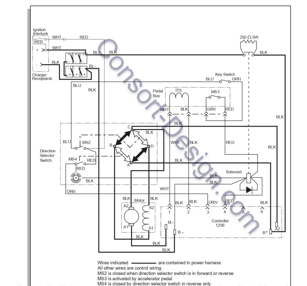
A diode is positioned between the two coil terminals of the solenoid. The cathode side of the diode which has a silver band is oriented to the solenoid terminal with the red wire attached. The positioning of the diode is important to ensure the pedal box micro switch and the direction selector micro switch are not damaged The Ezgo speed controller wiring diagram found in the manual shows the outline of the pedal box assembly and its function.
The following diagram shows the wiring system of the Ezgo controller and control system (36 V).

Troubleshooting The Ezgo Controller And Control System.
The Ezgo speed control system is essential for the acceleration and handling of the Ezgo utility vehicle. As such if it becomes faulty the vehicle may not operate or it may operate poorly or intermittently. The troubleshooting of the Ezgo control system and Ezgo control wiring system is important in addressing the problem.
Ezgo Battery Troubleshooting
When troubleshooting the Ezgo utility vehicle start testing the battery. The open circuit voltage test can be misleading, since even a deteriorated battery can show six volts or higher in an open voltage test. It is advisable therefore to carry out a load test using a discharge machine and following the manufacturer instructions. After confirming the adequacy of the batteries, use the digital volt ohm meter (DVOM) preferably the P/N 27481-G01. To assure accurate readings, the meter should be set to the closest voltage reading above the expected voltage. Some loss due to resistance of the wires and connectors may be indicated by readings that could be up to one volt less than the reference voltage. No readings usually indicate an open connection and the battery wires should be inspected for a broken or disconnected wires. The battery reference voltage is usually around 37V. To prevent possible injury or death resulting from a battery explosion, use an insulated wrench and remove the battery negative wire from the battery to disconnect electrical power to the vehicle. The Ezgo speed control wiring diagram can be of great use in showing which wires to test.
Testing The Speed Control And Acceleration
When testing the acceleration and speed control, place the direction selector in ‘F’, forward and turn the key switch to ‘on’. Depress the accelerator pedal until the micro switch in the pedal box activates which should cause the solenoid to make an audible click. To prevent any injury from unexpected movement of the vehicle always raise the rear wheels before conducting any tests and support on jack stands. To prevent any damage to the motor and speed control wiring, never operate the vehicle at full throttle for more than 4-5 seconds while the vehicle is in a “no-load” condition.
Continuity Check
The next step in troubleshooting the Ezgo speed control system is carrying out a continuity check using a digital volt ohm meter (DVOM). The speed control wiring diagram can be of great use in showing the several wire connections that need to be tested. Before attempting to perform a continuity check, turn the key switch to ‘OFF’, place the direction selector to neutral and disconnect the battery power by removing the positive terminal. Ensure to check the pedal micro switch, neutral micro witch (direction selector switch), solenoid key switch and four pin connectors for continuity if the solenoid does not function. Ensure to use insulated wrenches. Use the DVOM set to KΩ and select ‘continuity’. The meter should give an audible signal.
Testing The Switch For Continuity
To test for continuity on the Ezgo speed control switch, place one probe of the DVOM on one contact of the switch and the second probe on the second terminal of the switch. Actuating a normally open (NO) switch will cause the DVOM to show “0” or give an audible indication. A normally closed switch (NC) will show “0” on the meter or give an audible indication when the probes are attached without activating switch. The audible indication will stop and the meter display will indicate a value greater than “0” when the switch is activated. The change in display or audible indicator demonstrates that the switch is functioning. Malfunction of the Ezgo speed control switch can indicate damage to the wiring hence it needs to be checked to ensure it functions as intended.
Testing a Solenoid For Continuity
To test the Ezgo solenoid for continuity place one probe of the DVOM on one of the large terminals of the solenoid and the other probe on the second large terminal. If the meter shows “0” or gives an audible indication, the solenoid terminals are “welded” closed and the solenoid must be replaced. If the Ezgo solenoid is found to be faulty which can due to its wiring, disconnect the battery negative terminal and short the controller negative and positive terminals using a screwdriver. Be sure to hold the screw driver using the insulated position. Remove the environmental cover and remove the solenoid bolts. Mount a new solenoid and tighten its. Replace the environmental cover and tighten its bolts before reconnecting the battery.
Inductive Throttle Sensor (Its) Testing And Replacement
One essential component of the Ezgo speed control system is the ITS (Inductive Throttle Sensor). This component works together with the Ezgo speed controller to ensure the vehicle speed control is as precise as possible. Troubleshooting of this component is essential to ensure the speed control system functions as intended. The ITS is found in the pedal box under the floor mate. To test the ITS apply the apply parking brake, and with a DVOM set to volts, probe the white wire at the ITS with the positive probe of the DVOM and attach the negative probe to the battery negative. Place the direction selector to forward and turn the keys to ‘ON’. Depress the accelerator pedal and as the solenoid clicks the meter should read 0.4 to 0.6 volts. The meter should read 1.5 to 1.7 volts at full pedal and if the reading exceeds the limits, the ITS sensor must be replaced. The ITS attaches to the plastic pedal box using two plastic studs and two speed nuts. Care is needed not to over tighten the nuts which could strip the plastic studs while tightening the nuts enough to prevent movement of the ITS.
Ezgo Speed Controller Replacement
The Ezgo speed controller is essential for the vehicle speed control as such when it misbehaves, there is need to replace it. To prevent electrical shock from the speed controller, disconnect the battery negative terminal then short the positive and negative controller terminals using a large screwdriver. The screwdriver should be held using the insulated potion. The direction selector should be covered using a shop towel. To replace the speed controller, remove the environmental cover and note the wiring on the controller before removing it. Remove the controller mounting bolts and remove the controller to inset a new one. After mounting the new controller tighten the controller. Replace the environmental cover and tighten its bolts before reconnecting the battery and replacing the seat. The Ezgo speed controller wiring diagram can be of great use to show the wiring of the controller.
Conclusion
In conclusion the Ezgo speed control wiring system is essential to the running of the vehicle, it ensures all the components receive the required voltage and current demands as such troubleshooting of the speed control wiring is essential to ensure there are no damaged or broken items that may hinder its performance.